Water Level Sensor
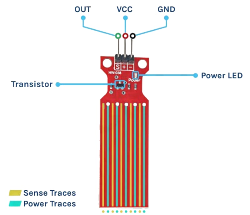
The water level sensor (also called a rain sensor or water depth sensor) is a set of exposed parallel traces on a PCB that act as a variable resistor. Water bridging the traces lowers the resistance proportionally to the depth of immersion. An LM393 comparator on the module provides both analog output (AO, varying voltage) and digital output (DO, HIGH/LOW with a potentiometer threshold). The sensor is used for water tank level monitoring, rain detection, and flood alarms.
For this interfacing you need the following components:
- Arduino board (Uno, Nano, Mega, etc.)
- Water level sensor module (with LM393 comparator, e.g., HW-038)
- Breadboard and jumper wires
- USB cable to connect Arduino to your computer
- (Optional) Small container of water for testing
Schematic
Water Level Module     Arduino
-----------------      -------
VCC           -->      5V
GND           -->      GND
AO (Analog)   -->      A0
DO (Digital)  -->      Digital Pin 2
The module has two separate sections: the sensing probe (exposed traces) and the LM393 comparator board.
Pin Map
| Module Pin | Name | Arduino Connection |
|---|---|---|
| VCC | Power | 5V |
| GND | Ground | GND |
| AO | Analog output (0–5V) | A0 |
| DO | Digital output (HIGH/LOW) | Pin 2 |
- AO: higher voltage = more water (lower resistance).
- DO: LOW when water level exceeds the potentiometer threshold.
- Onboard potentiometer sets the digital threshold.
Install necessary Library
No library is required. The sensor is read with analogRead() for the analog output and digitalRead() for the digital threshold.
Code with complete explanation
This sketch reads the water level, maps it to a percentage, and controls LEDs for dry/moist/wet status.
#define AO_PIN  A0
#define DO_PIN  2
#define LED_DRY    12  // Green — dry
#define LED_MOIST  11  // Yellow — moist
#define LED_WET    10  // Red — wet

void setup()
{
  Serial.begin(9600);
  pinMode(DO_PIN, INPUT);
  pinMode(LED_DRY, OUTPUT);
  pinMode(LED_MOIST, OUTPUT);
  pinMode(LED_WET, OUTPUT);
  Serial.println("Water Level Sensor Test");
}

void loop()
{
  int adc = analogRead(AO_PIN);    // 0–1023
  int pct = map(adc, 0, 750, 0, 100);
  pct = constrain(pct, 0, 100);

  int digitalVal = digitalRead(DO_PIN); // LOW = wet

  Serial.print("ADC: ");
  Serial.print(adc);
  Serial.print("  Level: ");
  Serial.print(pct);
  Serial.print("%  Digital: ");
  Serial.println(digitalVal == LOW ? "WET" : "DRY");

  // LED indication with hysteresis
  if (pct >= 70)
  {
    digitalWrite(LED_WET, HIGH);
    digitalWrite(LED_MOIST, LOW);
    digitalWrite(LED_DRY, LOW);
  }
  else if (pct >= 30)
  {
    digitalWrite(LED_WET, LOW);
    digitalWrite(LED_MOIST, HIGH);
    digitalWrite(LED_DRY, LOW);
  }
  else
  {
    digitalWrite(LED_WET, LOW);
    digitalWrite(LED_MOIST, LOW);
    digitalWrite(LED_DRY, HIGH);
  }

  delay(200);
}
Rain detector with alarm
#define BUZZER_PIN 3

void setup()
{
  pinMode(BUZZER_PIN, OUTPUT);
  pinMode(DO_PIN, INPUT);
}

void loop()
{
  if (digitalRead(DO_PIN) == LOW)
  {
    // Rain detected — sound alarm
    for (int i = 0; i < 5; i++)
    {
      tone(BUZZER_PIN, 2000, 100);
      delay(150);
    }

    delay(5000);  // Wait before next check
  }
  else
  {
    noTone(BUZZER_PIN);
  }

  delay(100);
}
Water tank with multiple sensors (high/low float switches)
For a discrete-level water tank monitor, use float switches (non-corrosive) instead of exposed traces:
#define LOW_FLOAT  4   // LOW when water is at minimum level
#define HIGH_FLOAT 5   // LOW when water is at maximum level
#define PUMP_RELAY 6

void setup()
{
  pinMode(LOW_FLOAT, INPUT_PULLUP);
  pinMode(HIGH_FLOAT, INPUT_PULLUP);
  pinMode(PUMP_RELAY, OUTPUT);
}

void loop()
{
  bool low  = (digitalRead(LOW_FLOAT) == LOW);   // Water at low mark
  bool high = (digitalRead(HIGH_FLOAT) == LOW);  // Water at high mark

  if (low && !high)
  {
    digitalWrite(PUMP_RELAY, HIGH);  // Pump on — tank empty
  }
  else if (high)
  {
    digitalWrite(PUMP_RELAY, LOW);   // Pump off — tank full
  }

  // If between low and high, maintain current state
}
Code breakdown
analogRead(AO_PIN)— returns the analog voltage from the sensor (0–1023). The ADC reading increases as water covers more traces because the water’s conductivity reduces the probe’s resistance.map(value, 0, 750, 0, 100)— maps the raw ADC to a percentage. The maximum ADC with the probe fully submerged is typically 600–800 (not 1023) because the sensor’s output does not reach 5V. Calibrate this range for your specific module.digitalRead(DO_PIN)— returnsLOWwhen the water level exceeds the threshold set by the onboard potentiometer.- The LED indication uses three discrete levels (dry < 30%, moist 30–70%, wet ≥ 70%) with hysteresis implicitly avoided by non-overlapping thresholds.
- The rain detector triggers a buzzer alarm when the digital pin goes LOW (wet). The 5-second delay prevents repeated triggering in light rain.
- The float switch approach uses
INPUT_PULLUP— the switch connects the pin to GND when activated (LOW = water present).
Calibration
void calibrate()
{
  // Dry sensor — record baseline
  int dryVal = analogRead(AO_PIN);

  // Fully submerged — record maximum
  int wetVal = analogRead(AO_PIN);

  // Map raw values to 0–100 %
  pct = map(adc, dryVal, wetVal, 0, 100);
  pct = constrain(pct, 0, 100);
}
Steps to perform this interfacing
- Connect the water level sensor module to the Arduino as shown.
- No library installation needed.
- Copy the code into the Arduino IDE.
- Select the correct board and port (
Tools > BoardandTools > Port). - Upload the sketch to the Arduino.
- Open the Serial Monitor (
Tools > Serial Monitor, set baud rate to 9600). - With the sensor dry, observe the ADC reading (typically 0–50).
- Dip the sensor into a container of water (do not submerge the LM393 board).
- Observe the ADC value increase — the green LED turns off, yellow then red turn on.
- Adjust the potentiometer on the module to change the digital threshold.
Caution
- ⚠️ Corrosion and electrochemical degradation: The water level sensor’s exposed copper traces are subject to electrolysis when DC current passes through water. Within hours of continuous use, the copper traces begin to corrode, turning green and eventually dissolving. This is the single biggest limitation of this sensor type. To mitigate: power the sensor only during measurement (pulse the VCC pin via a MOSFET or digital pin, read immediately, then power off). Even with this technique, lifespan is limited to weeks to months in continuous use.
- Pulsed operation to prevent corrosion:
#define SENSOR_PWR 8   // MOSFET gate or digital pin to power sensor VCC

void readSensor()
{
  digitalWrite(SENSOR_PWR, HIGH);   // Power on sensor
  delay(50);                         // Wait for stabilisation
  int val = analogRead(AO_PIN);     // Read
  digitalWrite(SENSOR_PWR, LOW);    // Power off immediately
}
- Not for potable water: The exposed copper traces and solder joints contain lead and other metals that leach into water. Do not use this sensor for drinking water, hydroponic nutrient solutions, or fish tanks. The corrosion products are toxic. For potable applications, use a pressure sensor, ultrasonic distance sensor (HC-SR04), or a stainless-steel capacitive sensor.
- Water conductivity varies: Tap water has higher conductivity (lower resistance) than distilled water. Saltwater has much higher conductivity. The analog reading for “full” varies significantly with water type. If the sensor is used in different water sources, auto-calibrate on each power-up or use a reference measurement.
- Comparator module must stay dry: The LM393 comparator board is not waterproof. If the module is immersed past the sensing trace area, water will short-circuit the electronics and destroy the module. Mount the comparator board above the maximum water level and extend the sensor probe with wires if needed.
- Maximum immersion depth: Most water level sensor modules are designed for a maximum immersion depth of ≈ 4–5 cm (the length of the exposed traces). For deeper tanks, use multiple sensors at different heights or a different sensing technology (ultrasonic, pressure, capacitive probe).
- Digital threshold potentiometer: The small potentiometer on the module is fragile. Turn it gently with a plastic screwdriver. Over-tightening or using a metal screwdriver can damage the wiper. Use a dab of nail polish or hot glue to lock the threshold once set.
- Float switch alternative: For reliable industrial-grade water level sensing, use a reed switch float sensor (magnetic float + reed switch). These have no corrosion issues, last millions of cycles, and are safe for drinking water. They provide only discrete levels (one switch = one threshold), but multiple floats can be combined for multi-level detection.