UV Sensor (ML8511 / GUVA-S12D)
Ultraviolet (UV) sensors measure the intensity of UV radiation in the 200–400 nm range. Two common modules for Arduino are:
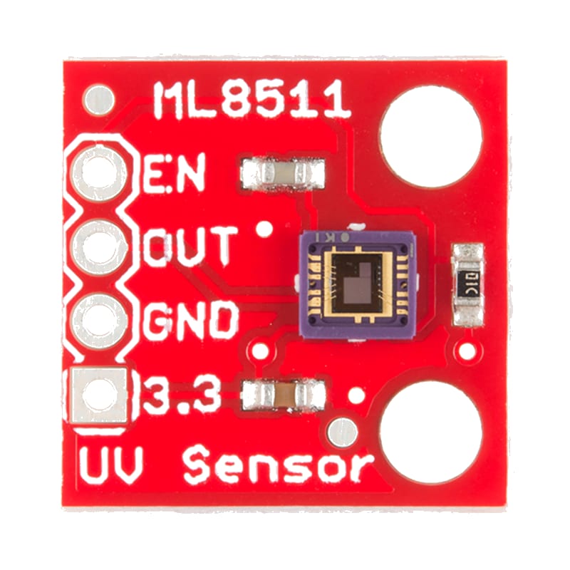
- ML8511 — analog output (1–3.2 V) proportional to UV intensity, requires 3.3V power.
- GUVA-S12D — analog output (0–5 V) proportional to UV index, operates at 5V.
Both sensors output a voltage that can be read with analogRead() and converted to a UV index value (0–11+), making them suitable for sun exposure monitoring, UV index meters, and environmental sensing.

For this interfacing you need the following components:
- Arduino board (Uno, Nano, Mega, etc.)
- UV sensor module: ML8511 or GUVA-S12D
- Breadboard and jumper wires
- USB cable to connect Arduino to your computer
Schematic
ML8511 wiring
ML8511 Module         Arduino
-------------         -------
VCC           -->     3.3V (NOT 5V — ML8511 is 3.3V only)
GND           -->     GND
OUT           -->     Analog Pin A0
EN            -->     3.3V (enable pin, active HIGH)
The ML8511 must be powered from 3.3V. The output voltage ranges from approximately 1 V (min UV) to 3.2 V (max UV).
GUVA-S12D wiring
GUVA-S12D Module      Arduino
----------------      -------
VCC           -->     5V
GND           -->     GND
OUT           -->     Analog Pin A0
The GUVA-S12D is powered from 5V and outputs 0–5V proportional to UV intensity.
Pin Map
ML8511
| Module Pin | Name | Connection |
|---|---|---|
| VCC | Power | 3.3V (NOT 5V) |
| GND | Ground | GND |
| OUT | Analog output | A0 |
| EN | Enable (active HIGH) | 3.3V |
GUVA-S12D
| Module Pin | Name | Connection |
|---|---|---|
| VCC | Power | 5V |
| GND | Ground | GND |
| OUT | Analog output | A0 |
Install necessary Library
No external library is required. The UV sensor uses standard analogRead() built into Arduino.
Code with complete explanation
This sketch reads the UV sensor output voltage and calculates the UV index. It includes both the ML8511 and GUVA-S12D conversion methods — uncomment the appropriate section.
const int sensorPin = A0;

// Select your sensor type
#define ML8511    1
// #define GUVA_S12D 1

void setup()
{
  Serial.begin(9600);
  Serial.println("UV Sensor Test");
}

void loop()
{
  int raw = analogRead(sensorPin);
  float voltage = raw * (5.0 / 1023.0);

#if defined(ML8511)
  // ML8511: 1V = UV index 0, 3.2V = UV index ~15
  // Output range: 0–3.2V (but at 3.3V VCC, max is ~3.2V)
  // UV Index = (Vout - 0.99) * (15.0 / (3.2 - 0.99))
  float uvIndex = (voltage - 0.99) * 6.79;
  if (uvIndex < 0) uvIndex = 0;

#elif defined(GUVA_S12D)
  // GUVA-S12D: 0V = UV index 0, 5V = UV index ~11
  // UV Index = Vout / 0.4545 (approximately)
  float uvIndex = voltage / 0.4545;

#else
  // Generic: assume 0–5V maps to UV index 0–11
  float uvIndex = (voltage / 5.0) * 11.0;
#endif

  Serial.print("Raw: ");
  Serial.print(raw);
  Serial.print("  Voltage: ");
  Serial.print(voltage, 3);
  Serial.print(" V  UV Index: ");
  Serial.print(uvIndex, 1);

  // Interpret UV index
  Serial.print(" - ");
  if (uvIndex < 3)
  {
    Serial.print("Low");
  }
  else if (uvIndex < 6)
  {
    Serial.print("Moderate");
  }
  else if (uvIndex < 8)
  {
    Serial.print("High");
  }
  else if (uvIndex < 11)
  {
    Serial.print("Very High");
  }
  else
  {
    Serial.print("Extreme");
  }

  Serial.println();
  delay(1000);
}
Code breakdown
analogRead(sensorPin)— reads the analog voltage (0–1023) from the UV sensor output.raw * (5.0 / 1023.0)— converts the raw ADC value to voltage. For the ML8511, the actual VCC is 3.3V, but sinceanalogReference(DEFAULT)is 5V, the formula uses 5.0/1023. The voltage reading is relative to the 5V reference, so outputs must be scaled accordingly.- ML8511 formula:
(voltage - 0.99) * 6.79. The offset voltage (0.99 V) is subtracted, then the remainder is scaled to the UV index range (0–15 for 1.0–3.2 V). - GUVA-S12D formula:
voltage / 0.4545. The sensor outputs approximately 0.4545 V per UV index unit.
ML8511 with 3.3V reference (more accurate)
For the ML8511, using the 3.3V analog reference improves accuracy because the sensor’s VCC is also 3.3V:
void setup()
{
  analogReference(EXTERNAL); // Connect 3.3V to AREF pin via 5 kΩ
  // WARNING: Do NOT use this if AREF is floating or connected to > 5V
}

void loop()
{
  int raw = analogRead(sensorPin);
  float voltage = raw * (3.3 / 1023.0);
  // ... rest of ML8511 calculation
}
Calibration check
UV sensor modules have unit-to-unit variation. For best accuracy, compare your readings against a reference UV index (e.g., your local weather bureau’s reported UV index) and adjust the scaling factor to match.
Example adjustment:
// If the reported UV index is 6 but your sensor reads 5.2:
// New scale = old scale × (6.0 / 5.2)
float uvIndex = (voltage - 0.99) * 6.79 * (6.0 / 5.2);
Steps to perform this interfacing
- Connect the UV sensor to the Arduino as shown in the schematic — ensure the ML8511 uses 3.3V and not 5V.
- Uncomment the appropriate sensor definition (
#define ML8511or#define GUVA_S12D) in the code. - Copy the code into the Arduino IDE.
- Select the correct board and port (
Tools > BoardandTools > Port). - Upload the sketch to the Arduino.
- Open the Serial Monitor (
Tools > Serial Monitor, set baud rate to 9600). - Observe the UV index reading. Indoors, the value should be near zero. Take the sensor outside in sunlight to see the UV index rise.
- Compare the reading with your local weather service’s reported UV index and adjust the calibration factor if needed.
Caution
- ML8511 voltage requirement: The ML8511 is a 3.3V only device. Connecting VCC to 5V will permanently damage it. The output voltage also scales with VCC, so powering it from 5V would produce incorrect readings even if the IC survives.
- Sensor response time: The UV sensor responds slowly to changes — allow 1–3 seconds for the reading to stabilize after moving from shade to sunlight or vice versa. The photodiode has a settling time of approximately 1 second.
- Spectral range: The ML8511 and GUVA-S12D are sensitive to UVA (315–400 nm) and UVB (280–315 nm). They do not measure UVC (100–280 nm), which is blocked by the ozone layer. The output is weighted to approximate the erythemal (sunburn) action spectrum, so the UV index reading is most relevant for human skin exposure.
- Temperature dependence: UV sensor output has a small temperature coefficient (approximately −0.1% per °C). For outdoor use in extreme temperatures (−20°C to +50°C), the reading may shift by ±5%. The ML8511 includes a temperature compensation circuit, but the GUVA-S12D does not.
- Diffuser needed: For accurate UV index measurements, the sensor should have a diffuser (white PTFE tape or an optical diffuser cap) over the photodiode to achieve a cosine-corrected response. Without a diffuser, the reading depends heavily on the angle of the incident UV light.
- Window glass blocks UV: The sensor will read near-zero UV indoors behind standard window glass because glass blocks most UVB. If you need to measure UV through glass, use an explicitly UV-transparent material (quartz or special acrylic).
- EN pin (ML8511): The ML8511 has an enable pin that must be pulled HIGH for normal operation. If left floating or driven LOW, the output goes to 0 V. On some modules, the EN pin is already pulled HIGH with a resistor — if not, connect it to 3.3V.