Line Follower Sensor (TCRT5000)
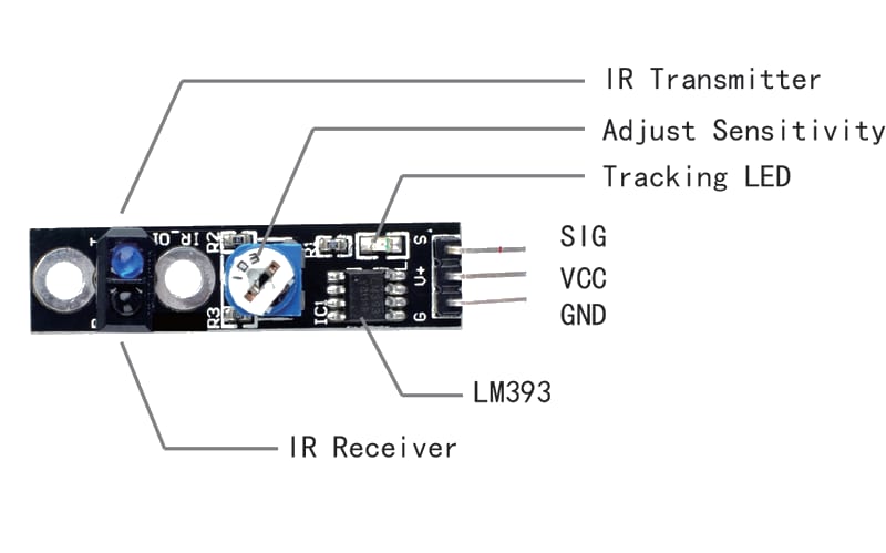
The TCRT5000 is a reflective optical sensor that pairs an infrared (IR) LED with a phototransistor. The amount of IR light reflected back changes depending on the surface colour — white/light surfaces reflect more IR, dark/black surfaces absorb IR. The module provides both an analog output (AO, proportional to reflectivity) and a digital output (DO, HIGH/LOW via an onboard comparator with a potentiometer threshold). It is the standard sensor for line-following robots.
For this interfacing you need the following components:
- Arduino board (Uno, Nano, Mega, etc.)
- TCRT5000 line follower sensor module (or similar: QRE1113, IR reflectance)
- Breadboard and jumper wires
- USB cable to connect Arduino to your computer
- (Optional) A black line on a white surface for testing
Schematic
TCRT5000 Module       Arduino
---------------       -------
VCC           -->     5V
GND           -->     GND
AO (Analog)   -->     A0
DO (Digital)  -->     Digital Pin 2
The module has two LEDs: a red power indicator and a green DO indicator (lit when the sensor detects a dark surface).
Pin Map
| Module Pin | Name | Arduino Connection |
|---|---|---|
| VCC | Power | 5V |
| GND | Ground | GND |
| AO | Analog output (0–5V) | A0 |
| DO | Digital output (HIGH/LOW) | Pin 2 |
- AO voltage is ≈ 5V on white, ≈ 0V on black.
- DO is LOW (LED on) when the surface is dark (below threshold), HIGH on light surface.
Threshold adjustment
The onboard potentiometer sets the digital switching threshold. Rotating clockwise raises the threshold (sensor triggers on darker surfaces). Rotating anticlockwise lowers it (triggers on lighter surfaces).
Install necessary Library
No library is required — the sensor is read with analogRead() and digitalRead(). The Arduino built-in analogRead() on A0 returns 0–1023 corresponding to 0–5V.
Code with complete explanation
This sketch reads both the analog and digital outputs of the TCRT5000 and prints the values, colour state, and line-following steering logic to the Serial Monitor.
#define SENSOR_AO  A0
#define SENSOR_DO  2

void setup()
{
  Serial.begin(9600);
  pinMode(SENSOR_DO, INPUT);
}

void loop()
{
  int analogValue  = analogRead(SENSOR_AO);   // 0–1023
  int digitalValue = digitalRead(SENSOR_DO);  // HIGH or LOW

  // Voltage on AO pin
  float voltage = analogValue * (5.0f / 1023.0f);

  // Determine surface colour
  const char* surface = (digitalValue == LOW) ? "DARK (black)" : "LIGHT (white)";

  Serial.print("Analog: ");
  Serial.print(analogValue);
  Serial.print("  Voltage: ");
  Serial.print(voltage, 3);
  Serial.print(" V  Digital: ");
  Serial.print(digitalValue);
  Serial.print("  Surface: ");
  Serial.println(surface);

  // --- Simple line-follower logic ---
  // Use a single sensor to detect line edge:

  if (digitalValue == LOW)
  {
    // Sensor is over the dark line
    Serial.println(">> ON LINE — turn or adjust");
  }
  else
  {
    // Sensor is over the light surface
    Serial.println(">> OFF LINE — go straight");
  }

  delay(200);
}
Code breakdown
analogRead(A0)— returns the raw 10-bit ADC value (0–1023) proportional to the IR reflectivity. Higher values = more IR reflected = lighter surface.digitalRead(DO)— returnsLOWwhen the surface is darker than the potentiometer threshold (IR absorbed),HIGHwhen lighter (IR reflected).- Threshold adjustment: the potentiometer sets the comparator reference voltage. Turn clockwise to make the sensor less sensitive (needs darker surface to trigger).
- The voltage calculation converts the ADC reading to an approximate voltage for debugging.
Multiple sensors for line following
Two sensors mounted side by side enable PID-style line following:
#define LEFT_SENSOR  A0
#define RIGHT_SENSOR A1

void loop()
{
  int left  = analogRead(LEFT_SENSOR);
  int right = analogRead(RIGHT_SENSOR);

  int left_grey  = left  > 500 ? 1 : 0;  // 1 = light, 0 = dark
  int right_grey = right > 500 ? 1 : 0;

  // Lookup table for motor control
  if      (left_grey == 0 && right_grey == 0) ;  // Both on line — go straight
  else if (left_grey == 1 && right_grey == 0) ;  // Left off line — turn left
  else if (left_grey == 0 && right_grey == 1) ;  // Right off line — turn right
  else if (left_grey == 1 && right_grey == 1) ;  // Both off line — stop / lost

  delay(20);
}
For more precise control, use the analog values directly as input to a PID controller that steers the motors proportionally.
Steps to perform this interfacing
- Connect the TCRT5000 module to the Arduino as shown in the schematic.
- No library installation needed.
- Copy the code into the Arduino IDE.
- Select the correct board and port (
Tools > BoardandTools > Port). - Upload the sketch to the Arduino.
- Open the Serial Monitor (
Tools > Serial Monitor, set baud rate to 9600). - Hold the sensor 5–15 mm above a white surface — you should see “LIGHT (white)” and a high analog value.
- Hold it above a black line or dark surface — you should see “DARK (black)” and a low analog value.
- Adjust the potentiometer on the module until the digital output reliably switches at the desired threshold.
Calibration tips
- The ideal sensing distance is 5–15 mm from the surface. Too far and the IR beam spreads too wide; too close and the sensor saturates.
- The analog threshold on a white surface is typically 600–900 (ADC). On black, it drops to 50–200. Tune the potentiometer so the DO pin triggers at ≈500 ADC.
- Ambient IR (sunlight, incandescent bulbs) can affect readings. Adding a hood or enclosure around the sensor helps.
Caution
- Sensing distance: The TCRT5000 is designed for a detection distance of 2–15 mm. At distances beyond 15 mm, the reflected IR signal drops off sharply, and the sensor may not reliably distinguish between black and white surfaces. Mount the sensor close to the ground on a robot chassis.
- Glossy surfaces: The sensor uses IR light, which reflects specularly off glossy surfaces (e.g., laminated paper, polished floors). This can cause false readings because the reflected beam may miss the phototransistor. Matte surfaces are preferred for line-following tracks.
- Ambient IR interference: Bright sunlight contains significant IR that can saturate the phototransistor, rendering the sensor blind. The TCRT5000 should be used indoors or with a physical shield that blocks ambient IR while allowing the sensor’s own IR beam to reflect.
- Multiple sensor crosstalk: When using multiple TCRT5000 modules side by side, the IR LED from one sensor can bleed into the phototransistor of the adjacent sensor, causing false readings. Space sensors ≥ 15 mm apart or strobe them (turn on one IR LED at a time while reading its phototransistor).
- Power consumption: Each TCRT5000 module draws approximately 10–15 mA (the IR LED is the main consumer). A robot with 8 line sensors will draw 80–120 mA for the sensors alone — factor this into the total current budget.
- Black line colour: The sensor works best with black or very dark blue lines on a white or very light background. Grey lines or dark green backgrounds may not provide enough contrast for reliable detection. Red and other colours absorb different IR wavelengths — test with your specific surface.