Stepper Motor – Accurate positioning
A stepper motor moves in discrete steps, allowing precise position and speed control without feedback. Each full rotation is divided into an equal number of steps (e.g., 200 steps/rev for a NEMA 17, or 64 steps/rev for a 28BYJ-48 before gearing). Steppers are used in 3D printers, CNC machines, camera sliders, and any application requiring accurate rotary or linear positioning.
This tutorial covers two common setups:
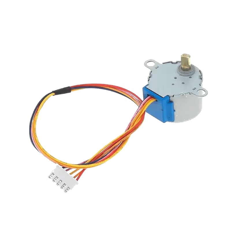
- 28BYJ-48 (unipolar, 5V) with ULN2003 driver board — low cost, low torque
- NEMA 17 (bipolar, 12–24V) with A4988 driver — higher torque, microstepping
For this interfacing you need the following components:
- Arduino board (Uno, Nano, Mega, etc.)
- Stepper motor: 28BYJ-48 (5V unipolar) or NEMA 17 (bipolar)
- Driver: ULN2003 (for 28BYJ-48) or A4988 (for NEMA 17)
- Breadboard and jumper wires
- External power supply (9V / 1A for 28BYJ-48; 12V / 2A for NEMA 17)
- 100 µF capacitor (for A4988 power input)
- USB cable to connect Arduino to your computer
Schematic
28BYJ-48 with ULN2003 driver
ULN2003 Driver        Arduino
---------------       -------
IN1           -->     Digital Pin 8
IN2           -->     Digital Pin 9
IN3           -->     Digital Pin 10
IN4           -->     Digital Pin 11
VCC (+, 5V)   -->     5V (or external 5–12V supply)
GND (-)       -->     GND (common)

28BYJ-48 motor plugs directly into the ULN2003 driver board header.
The 28BYJ-48 is a 5V unipolar stepper with a 64:1 gearbox (4096 steps per revolution in full-step mode).
NEMA 17 with A4988 driver
A4988 Driver          Arduino
-------------         -------
STEP          -->     Digital Pin 3
DIR           -->     Digital Pin 2
ENABLE        -->     Digital Pin 4 (optional, LOW = enabled)
MS1           -->     GND (full step) / 5V (microstep)
MS2           -->     GND
MS3           -->     GND
VDD (logic)   -->     5V
GND           -->     GND
VMOT (power)  -->     12V (external PSU)
GND (power)   -->     GND (common with PSU and Arduino)

NEMA 17 coils -->     A4988 outputs (1A, 1B, 2A, 2B)
100 µF cap    -->     across VMOT and GND (near driver)

External 12V (+) -->  VMOT
External 12V (-) -->  GND (common)
The A4988 handles current limiting and microstepping. Set the current limit to match your NEMA 17 motor before operation.
Pin Map
28BYJ-48 wire colours (unipolar)
| Motor Wire | ULN2003 Pin | Arduino Pin |
|---|---|---|
| Blue | IN1 | 8 |
| Pink | IN2 | 9 |
| Yellow | IN3 | 10 |
| Orange | IN4 | 11 |
| Red (centre tap) | VCC (5V) | 5V |
A4988 pin map (NEMA 17 bipolar)
| A4988 Pin | Name | Connection |
|---|---|---|
| STEP | Step pulse | Pin 3 (any digital) |
| DIR | Direction | Pin 2 (HIGH = CW, LOW = CCW) |
| ENABLE | Enable driver | Pin 4 (LOW = enabled) |
| MS1, MS2, MS3 | Microstep selection | GND / 5V (see table) |
| VDD | Logic supply | 5V |
| GND | Logic ground | GND |
| VMOT | Motor supply | 8–35V DC |
| GND | Motor ground | GND (PSU common) |
| 1A, 1B | Coil A | NEMA 17 coil A |
| 2A, 2B | Coil B | NEMA 17 coil B |
Microstep selection (A4988)
| MS1 | MS2 | MS3 | Microstep Resolution |
|---|---|---|---|
| LOW | LOW | LOW | Full step (1) |
| HIGH | LOW | LOW | Half step (2) |
| LOW | HIGH | LOW | Quarter step (4) |
| HIGH | HIGH | LOW | Eighth step (8) |
| HIGH | HIGH | HIGH | Sixteenth step (16) |
Higher microstep resolution gives smoother motion at the cost of lower torque per step and higher step pulse frequency.
Install necessary Library
For basic control, the Stepper library is built into the Arduino IDE — no installation required:
#include <Stepper.h>
For advanced control (acceleration, deceleration, multi-motor, non-blocking moves), install the AccelStepper library by Mike McCauley via the Library Manager:
arduino-cli lib install "AccelStepper"
Code with complete explanation
Example 1: 28BYJ-48 with Stepper library
This sketch rotates the 28BYJ-48 motor forward 360° and backward 360° repeatedly.
#include <Stepper.h>

const int stepsPerRev = 2048; // 28BYJ-48: 64 steps × 64:1 gear ratio / 2 (half-step)
// For full-step mode: 4096 (64 × 64)
// For half-step mode (default): 2048

Stepper stepper(stepsPerRev, 8, 10, 9, 11);
// Order: stepsPerRev, IN1, IN3, IN2, IN4
// (not sequential — this matches the ULN2003 coil sequence)

void setup()
{
  stepper.setSpeed(10); // RPM (max ~15–20 for 28BYJ-48)
}

void loop()
{
  Serial.println("Forward 360°");
  stepper.step(stepsPerRev); // Rotate one full revolution
  delay(1000);

  Serial.println("Backward 360°");
  stepper.step(-stepsPerRev); // Reverse one full revolution
  delay(1000);
}
Example 2: 28BYJ-48 with AccelStepper (advanced)
#include <AccelStepper.h>

// Half-step driver: 4 pins (ULN2003)
AccelStepper stepper(AccelStepper::HALF4WIRE, 8, 10, 9, 11);

void setup()
{
  stepper.setMaxSpeed(1000);     // steps per second
  stepper.setAcceleration(500);  // steps per second²
  stepper.moveTo(4096);          // Move 4096 steps (one full revolution)
}

void loop()
{
  if (stepper.distanceToGo() == 0)
  {
    stepper.moveTo(-stepper.currentPosition()); // Reverse direction
  }

  stepper.run(); // Non-blocking step handler
}
Example 3: NEMA 17 with A4988 and AccelStepper
#include <AccelStepper.h>

#define STEP_PIN  3
#define DIR_PIN   2
#define ENABLE_PIN 4

AccelStepper stepper(AccelStepper::DRIVER, STEP_PIN, DIR_PIN);

void setup()
{
  pinMode(ENABLE_PIN, OUTPUT);
  digitalWrite(ENABLE_PIN, LOW); // Enable the driver

  stepper.setMaxSpeed(2000);     // steps per second
  stepper.setAcceleration(1000);
  stepper.setSpeed(500);
  stepper.moveTo(3200);          // NEMA 17 typical: 200 steps/rev × 16 microsteps
}

void loop()
{
  if (stepper.distanceToGo() == 0)
  {
    stepper.moveTo(-stepper.currentPosition());
  }

  stepper.run();
}
Code breakdown
#include <Stepper.h>— built-in library. Simple, blockingstep()calls.Stepper(stepsPerRev, pin1, pin3, pin2, pin4)— creates a stepper object. The pin order is specific to the ULN2003 coil sequence (not sequential).stepper.setSpeed(rpm)— sets the motor speed in RPM (max ~15–20 for 28BYJ-48).stepper.step(count)— moves the motor by the specified number of steps (positive = forward, negative = backward). This is blocking — the function does not return until the move completes.#include <AccelStepper.h>— advanced library supporting acceleration, non-blocking moves, and multiple motors.AccelStepper(driverType, step, dir)— for A4988/DRV8825:AccelStepper::DRIVERwith STEP and DIR pins.AccelStepper(driverType, pin1, pin3, pin2, pin4)— for ULN2003:AccelStepper::HALF4WIREorFULL4WIRE.stepper.setMaxSpeed(sps)— sets the maximum speed in steps per second.stepper.setAcceleration(sps²)— sets acceleration in steps per second².stepper.moveTo(position)— sets the target absolute position in steps. Non-blocking.stepper.distanceToGo()— returns the remaining steps to the target.stepper.run()— called repeatedly inloop(). Advances one step when needed. Returnstruewhile moving.stepper.setSpeed(sps)— sets a constant speed forrunSpeed()(no acceleration).stepper.currentPosition()— returns the current absolute position in steps.
Setting the A4988 current limit
Before using a NEMA 17 with an A4988, set the current limit to match your motor:
- Power the A4988 VDD (5V) but do not connect VMOT yet.
- Turn the trimpot fully counter-clockwise (minimum current).
- Measure the voltage between the trimpot and GND.
- Adjust until the voltage equals:
Vref = Imax × 8 × Rsensewhere Rsense is the value of the sense resistors (typically 0.1 Ω or 0.05 Ω — check your board).- For 0.1 Ω sense resistors: Vref = Imax × 0.8
- For a 1.2 A motor: Vref ≈ 0.96 V
- Power off, connect VMOT and the motor, then test.
Steps to perform this interfacing
For 28BYJ-48 + ULN2003
- Plug the 28BYJ-48 ribbon cable into the ULN2003 board (keyed connector).
- Connect ULN2003 IN1–IN4 to Arduino pins 8, 10, 9, 11.
- Connect ULN2003 VCC to 5V and GND to GND.
- Upload the Stepper library example code to the Arduino.
- Observe the motor rotating forward one revolution, pausing, then reversing.
For NEMA 17 + A4988
- Connect the A4988 to the Arduino as shown in the schematic.
- Place the 100 µF capacitor across VMOT and GND near the driver.
- Set the A4988 current limit for your motor.
- Select microstepping mode via MS1–MS3 pins.
- Connect the NEMA 17 coils to the A4988 outputs (check your motor datasheet for the coil wire pairs).
- Connect the external 12V power supply to VMOT and GND.
- Upload the AccelStepper example code.
- Observe the motor accelerating, rotating at speed, decelerating, and reversing.
Caution
- 28BYJ-48 power draw: The 28BYJ-48 draws 200–400 mA under load. Powering it from the Arduino 5V pin is acceptable for short tests, but for extended use, power the ULN2003 board from an external 5–12V supply while keeping the Arduino connected via USB or its own power supply.
- 28BYJ-48 gearbox: The internal plastic gears are delicate. Avoid forcing the output shaft manually — the gears strip easily. The gear ratio is 64:1, so the output shaft rotates very slowly compared to the internal rotor. Do not exceed 15–20 RPM on the output shaft.
- A4988 current limit: The A4988 does not have current-limiting resistors — you must set the current limit via the trimpot. Leaving the limit at the factory maximum will overheat and damage both the driver and the motor. Always adjust the limit for your specific motor before operation.
- A4988 minimum load: The A4988 must have a motor connected when powered. Running the driver without a motor on VMOT can damage the output stage. If testing without a motor, keep VMOT disconnected.
- A4988 reverse voltage: Do not connect VMOT in reverse polarity — the driver will be destroyed instantly. Use a polarity-protected supply or add a Schottky diode on the VMOT input.
- A4988 heat: The A4988 driver IC can become very hot (>80 °C) during operation at 1–2 A. Ensure adequate airflow or attach a small heatsink. If the driver enters thermal shutdown, it will stop until it cools.
- Common ground: For both setups, the motor power supply ground must be connected to the Arduino GND. Without a common ground, step signals will not return and the motor will not move.
- Step pulse timing: The A4988 requires a minimum STEP pulse width of 1 µs. The AccelStepper library handles this automatically. If writing your own stepping code, ensure the pulse is at least 2 µs HIGH and 2 µs LOW.
- Disconnecting while powered: Do not connect or disconnect the motor wires while the driver is powered. The back-EMF from the motor coils can damage the driver. Always power off before changing motor connections.