Soil Moisture (YL-69/HL-69) Sensor
The YL-69 (also sold as HL-69) soil moisture sensor measures the volumetric water content in soil by measuring the resistance between its two probes. It uses an LM393 comparator to provide both a digital (wet/dry) and an analog (moisture level) output, making it ideal for automated plant watering systems and garden monitoring.
For this interfacing you need the following components:
- Arduino board (Uno, Nano, Mega, etc.)
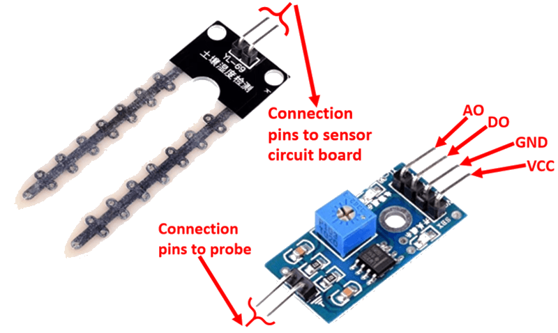
- YL-69 / HL-69 soil moisture sensor module (probes + control board)
- Breadboard and jumper wires (female-to-female for the sensor)
- USB cable to connect Arduino to your computer
Schematic
The sensor module has two parts: the soil probes and the control board. Connect the control board to the Arduino as follows:
Control Board         Arduino
-------------         -------
VCC           -->     5V
GND           -->     GND
DO            -->     Digital Pin 2
AO            -->     Analog Pin A0
Connect the soil probes to the control board via the spring terminals or header pins. The control board has a potentiometer that adjusts the digital output threshold — turn it with a screwdriver to set the dryness level that triggers the digital output.
Pin Map
Control Board
| Pin | Name | Connection |
|---|---|---|
| VCC | Power | 5V |
| GND | Ground | GND |
| DO | Digital Output | Any digital pin (pin 2 used) |
| AO | Analog Output | Any analog pin (A0 used) |
Probe
| Terminal | Connection |
|---|---|
| Two spring terminals | Connect to the two probe pins (polarity does not matter) |
Install necessary Library
No external library is required — soil moisture sensing uses standard digitalRead() and analogRead() functions built into Arduino.
Code with complete explanation
This sketch reads both the digital (wet/dry) and analog (moisture level) outputs, printing the values to the Serial Monitor. It also maps the analog reading to a percentage for easier interpretation.
const int digitalPin = 2; // DO pin
const int analogPin  = A0; // AO pin

void setup()
{
  Serial.begin(9600);
  pinMode(digitalPin, INPUT);
}

void loop()
{
  int digitalValue = digitalRead(digitalPin); // LOW = wet (below threshold)
  int analogValue  = analogRead(analogPin);   // 0–1023 (higher = more moisture)

  // Map analog value to moisture percentage (0–100%)
  // Dry air: ~0, Submerged: ~1023 (values vary by soil type)
  int moisturePercent = map(analogValue, 0, 1023, 0, 100);

  Serial.print("Digital: ");
  Serial.print(digitalValue);
  Serial.print(" (");

  if (digitalValue == LOW)
  {
    Serial.print("WET");
  }
  else
  {
    Serial.print("DRY");
  }

  Serial.print(")  Analog: ");
  Serial.print(analogValue);
  Serial.print("  Moisture: ");
  Serial.print(moisturePercent);
  Serial.print("% (");

  if (moisturePercent < 25)
  {
    Serial.print("Very dry");
  }
  else if (moisturePercent < 50)
  {
    Serial.print("Dry");
  }
  else if (moisturePercent < 75)
  {
    Serial.print("Moist");
  }
  else
  {
    Serial.print("Wet");
  }

  Serial.println(")");
  delay(500);
}
Code breakdown
digitalRead(digitalPin)— reads the DO pin. The LM393 comparator drives this pinLOWwhen moisture exceeds the threshold set by the onboard potentiometer. It isHIGHwhen the soil is dry.analogRead(analogPin)— reads the AO pin (0–1023). A higher value means more moisture because water reduces the resistance between the probes, allowing more current to flow.map(analogValue, 0, 1023, 0, 100)— converts the raw 10-bit analog reading to a 0–100% moisture scale. The actual range may vary depending on soil type and probe depth, so calibrating against known wet and dry samples gives more accurate results.
Steps to perform this interfacing
- Connect the soil probes to the control board via the spring terminals.
- Connect the control board to the Arduino as shown in the schematic.
- Copy the code into the Arduino IDE.
- Select the correct board and port (
Tools > BoardandTools > Port). - Upload the sketch to the Arduino.
- Open the Serial Monitor (
Tools > Serial Monitor, set baud rate to 9600). - Insert the probes into dry soil and observe the reading, then add water and watch the values increase.
- Adjust the sensitivity potentiometer on the control board to set the digital trigger point.
Caution
- The probes are subject to electrolysis when powered with DC current in a moist environment. This corrodes the probes over time. To extend probe life, power the sensor only when taking a reading — connect VCC to a digital pin and set it
HIGHfor 100 ms before reading, thenLOWafterward. - Do not insert the probes too close to plant roots — physical damage and root rot can occur.
- Calibration is soil-type dependent. Sandy soil, clay soil, and potting mix all have different conductivity baselines. Test with your specific soil before setting thresholds.
- Clean the probes with a dry cloth between uses to remove residue and prevent oxidation.
- The sensor is not suitable for submerged or water-logged environments for long periods. Use a capacitive soil moisture sensor instead for outdoor or long-term installations.