RGB LED
An RGB LED contains three individual LED dies (Red, Green, Blue) in a single package. By mixing the three colours with PWM, any colour in the visible spectrum can be produced. RGB LEDs come in common cathode (single GND pin, three anode pins) or common anode (single VCC pin, three cathode pins). Each channel requires its own current-limiting resistor.

For this interfacing you need the following components:
- Arduino board (Uno, Nano, Mega, etc.)
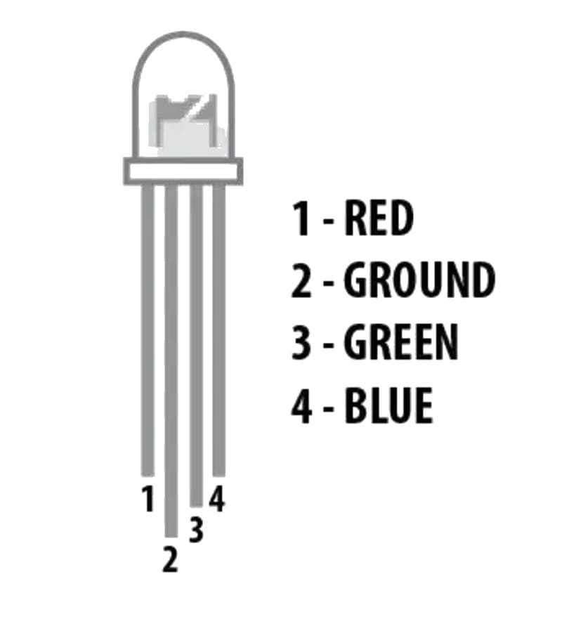
- 5 mm RGB LED (common cathode or common anode)
- 3 × 220 Ω resistors (or 100–470 Ω depending on brightness)
- Breadboard and jumper wires
- USB cable to connect Arduino to your computer
Schematic
Common cathode
Arduino           RGB LED (CC)
-------           ------------
Pin 9    ----[220Ω]---- R (Red anode)
Pin 10   ----[220Ω]---- G (Green anode)
Pin 11   ----[220Ω]---- B (Blue anode)
GND      -------------- - (Common cathode)
Common anode
Arduino           RGB LED (CA)
-------           ------------
Pin 9    ----[220Ω]---- R (Red cathode)
Pin 10   ----[220Ω]---- G (Green cathode)
Pin 11   ----[220Ω]---- B (Blue cathode)
5V       -------------- + (Common anode)
For common anode, the PWM logic is inverted — analogWrite(pin, 255) = LED off, analogWrite(pin, 0) = full brightness.
Pin Map
| LED Pin | Label | Arduino Pin | Resistor |
|---|---|---|---|
| Longest pin (CC) | Common cathode (-) | GND | None |
| Adjacent (R) | Red | 9 (PWM) | 220 Ω |
| Next (G) | Green | 10 (PWM) | 220 Ω |
| Shortest (B) | Blue | 11 (PWM) | 220 Ω |
Pin order varies by manufacturer — always check the datasheet. Common anode RGB LEDs have a common longest pin too (the anode).
Install necessary Library
No library is required. PWM control uses analogWrite().
Code with complete explanation
This sketch cycles through the colour wheel and allows manual colour control via serial commands.
#define PIN_RED   9
#define PIN_GREEN 10
#define PIN_BLUE  11

void setup()
{
  Serial.begin(9600);
  pinMode(PIN_RED,   OUTPUT);
  pinMode(PIN_GREEN, OUTPUT);
  pinMode(PIN_BLUE,  OUTPUT);

  Serial.println("RGB LED Colour Test");
  Serial.println("Commands:");
  Serial.println("  R<0-255>  — Set red brightness");
  Serial.println("  G<0-255>  — Set green brightness");
  Serial.println("  B<0-255>  — Set blue brightness");
  Serial.println("  C         — Cycle through colours");
}

void loop()
{
  if (Serial.available())
  {
    char cmd = Serial.read();

    switch (cmd)
    {
      case 'R':
        setColour(Serial.parseInt(), 0, 0);
        break;
      case 'G':
        setColour(0, Serial.parseInt(), 0);
        break;
      case 'B':
        setColour(0, 0, Serial.parseInt());
        break;
      case 'C':
        colourCycle();
        break;
    }

    Serial.read();  // Consume newline
  }
}

void setColour(int r, int g, int b)
{
  // For common cathode: 0 = off, 255 = full
  // For common anode:  255 = off, 0 = full
  analogWrite(PIN_RED,   constrain(r, 0, 255));
  analogWrite(PIN_GREEN, constrain(g, 0, 255));
  analogWrite(PIN_BLUE,  constrain(b, 0, 255));
}

void colourCycle()
{
  // Red → Yellow → Green → Cyan → Blue → Magenta → Red
  for (int i = 0; i <= 255; i++)
  {
    setColour(255, i, 0);      // Add green
    delay(5);
  }
  for (int i = 255; i >= 0; i--)
  {
    setColour(i, 255, 0);      // Remove red
    delay(5);
  }
  for (int i = 0; i <= 255; i++)
  {
    setColour(0, 255, i);      // Add blue
    delay(5);
  }
  for (int i = 255; i >= 0; i--)
  {
    setColour(0, i, 255);      // Remove green
    delay(5);
  }
  for (int i = 0; i <= 255; i++)
  {
    setColour(i, 0, 255);      // Add red
    delay(5);
  }
  for (int i = 255; i >= 0; i--)
  {
    setColour(255, 0, i);      // Remove blue
    delay(5);
  }
}
Common anode version helper
void setColourCA(int r, int g, int b)
{
  // Invert for common anode (255 = off, 0 = on)
  analogWrite(PIN_RED,   255 - constrain(r, 0, 255));
  analogWrite(PIN_GREEN, 255 - constrain(g, 0, 255));
  analogWrite(PIN_BLUE,  255 - constrain(b, 0, 255));
}
Predefined colours
void setColour(uint32_t hex)
{
  // hex = 0xRRGGBB
  int r = (hex >> 16) & 0xFF;
  int g = (hex >> 8)  & 0xFF;
  int b = hex         & 0xFF;
  setColour(r, g, b);
}

// Usage:
// setColour(0xFF0000);  // Red
// setColour(0x00FF00);  // Green
// setColour(0x0000FF);  // Blue
// setColour(0xFFFF00);  // Yellow
// setColour(0xFFFFFF);  // White
// setColour(0x000000);  // Off
Code breakdown
analogWrite(pin, value)— outputs a PWM signal (0–255) on the specified pin, controlling LED brightness.constrain(value, 0, 255)— clamps the input to the valid PWM range.Serial.parseInt()— reads an integer from the serial buffer (e.g., sendingR128sets red to 50%).- Colour mixing: roughly 8 million colours (256³) are possible but the human eye cannot distinguish adjacent shades at the low end. 64 levels per channel (6-bit) is often sufficient.
- The colour cycle cross-fades between primary and secondary colours by linearly interpolating two channels at a time.
Steps to perform this interfacing
- Identify whether your RGB LED is common cathode or common anode using a multimeter (diode test mode) or by looking at the longest pin.
- Connect three 220 Ω resistors to the R, G, B pins of the LED.
- Connect the resistor leads to PWM-capable Arduino pins (9, 10, 11).
- Connect the common pin to GND (cathode) or 5V (anode).
- Copy the code into the Arduino IDE.
- Select the correct board and port (
Tools > BoardandTools > Port). - Upload the sketch to the Arduino.
- Open the Serial Monitor (
Tools > Serial Monitor, set baud rate to 9600). - Type C to cycle through colours.
- Type R128 to set red to 50%, G255 for full green, B64 for dim blue.
- Try combinations: R255 + G255 = yellow, R128 + B128 = purple.
Caution
- Common anode requires inverted logic: If your LED is common anode and you use common cathode code (0–255), the LED will appear to work but with inverted brightness — full brightness = 0, off = 255. Always check the datasheet or use the helper function
setColourCA()above. Driving a common anode LED with common cathode code is safe (just looks wrong), but the reverse (CC with CA code) will not drive the LED at all. - Resistor selection: The forward voltage of each die differs: Red ≈ 1.8–2.2V, Green ≈ 3.0–3.4V, Blue ≈ 3.0–3.4V. With a 5V supply and 220 Ω resistor: Red current ≈ (5-2)/220 ≈ 14 mA, Blue current ≈ (5-3.2)/220 ≈ 8 mA. This is why white often looks pinkish — the red is brighter than blue/green. Balance the brightness by using different resistor values: e.g., 330 Ω (R) and 220 Ω (G, B). Or adjust the PWM levels in software to find a visually pleasing white.
- Maximum current per pin: The Arduino’s ATmega328P can source/sink a maximum of 40 mA per pin and 200 mA total across all pins. Full brightness on all three channels (3 × 20 mA = 60 mA) is within this limit, but if adding more LEDs, use a transistor or LED driver.
- Perceived brightness is not linear: The human eye perceives brightness logarithmically. A PWM value of 128 is not perceived as 50% brightness — it appears much brighter. For smooth fades, use a gamma-correction curve:
actual = pow(pct / 255.0, 2.8) * 255. - ESD sensitivity: The LED dies are sensitive to electrostatic discharge. When handling the LED, touch a grounded metal object first. Avoid touching the leads.
- RGB vs RGBW: Some RGB LEDs include a separate white die (RGBW) for truer whites. These require 4 PWM channels and 4 resistors. The code above controls only the R, G, B channels — leave the W pin unconnected or wire it to a 4th PWM pin.