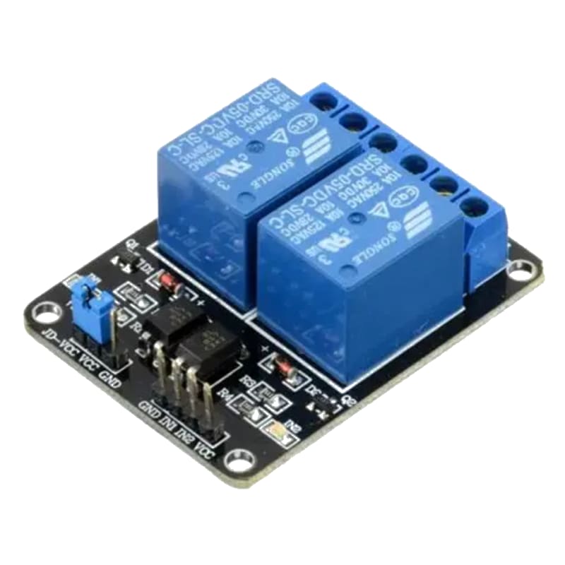
Relay Module
A relay is an electromechanical switch that allows a low-power Arduino signal to control high-power AC or DC loads. Common relay modules (1/2/4/8 channels) include optocoupler isolation, flyback diodes, and LED indicators, making them safe and easy to use for home automation, appliance control, and industrial switching.
Mains voltage connections
A relay’s output terminals have three connections:
| Terminal | Description |
|---|---|
| COM (Common) | The shared terminal — connect the live (phase) wire of the AC load here |
| NO (Normally Open) | The circuit is open when the relay is off. When activated, COM connects to NO, powering the load. |
| NC (Normally Closed) | The circuit is closed when the relay is off. When activated, COM disconnects from NC. |
For a typical light bulb or fan:
- Mains Live -> COM
- Mains Neutral -> Load neutral terminal
- Load live terminal -> NO (if you want the relay to turn it ON when activated)
Always switch the live (phase) wire, never the neutral. Use proper wire gauge for the current rating of your load.
For this interfacing you need the following components:
- Arduino board (Uno, Nano, Mega, etc.)
- Relay module (1-channel, 5V, active LOW)
- Load to control (e.g., incandescent bulb, fan, or DC motor for testing)
- External power supply for the load (if AC: use extreme caution)
- Breadboard and jumper wires
- USB cable to connect Arduino to your computer
Schematic
Connect the relay module to the Arduino as follows:
Relay Module          Arduino
------------          -------
VCC           -->     5V
GND           -->     GND
IN (or SIG)   -->     Digital Pin 7
For a DC test load (e.g., an LED or small DC motor):
External Circuit:
Relay COM     -->     External 9V Supply (+)
Relay NO      -->     Load positive terminal
Load negative -->     External 9V Supply (-)
For AC loads, refer to the Mains voltage connections section above. Do not test AC loads without proper knowledge and safety equipment.
Pin Map
| Module Pin | Connection |
|---|---|
| VCC | 5V (Arduino) |
| GND | GND (Arduino) |
| IN1 (or CH1, SIG) | Any digital pin (pin 7 used) |
| JD-VCC | (On some modules) External relay power — leave jumper connected to VCC for Arduino power |
Most 5V relay modules are active LOW: writing LOW to the IN pin activates the relay (clicks ON), and writing HIGH deactivates it. This is because the optocoupler LED is wired with its cathode to the IN pin.
Install necessary Library
No external library is required. Relay control uses standard digitalWrite().
Code with complete explanation
This sketch toggles a relay on and off every 2 seconds, simulating a blinking light or periodic appliance control.
const int relayPin = 7;

void setup()
{
  Serial.begin(9600);
  pinMode(relayPin, OUTPUT);

  // Start with relay off (HIGH = inactive for active-LOW modules)
  digitalWrite(relayPin, HIGH);
}

void loop()
{
  Serial.println("Relay ON");
  digitalWrite(relayPin, LOW);  // Active LOW: LOW = relay energized
  delay(2000);

  Serial.println("Relay OFF");
  digitalWrite(relayPin, HIGH); // HIGH = relay de-energized
  delay(2000);
}
Code breakdown
pinMode(relayPin, OUTPUT)— configures the control pin as an output.digitalWrite(relayPin, LOW)— most relay modules are active LOW, meaning the transistor driver turns on when the signal pin is pulled LOW. This is due to the optocoupler’s internal wiring.digitalWrite(relayPin, HIGH)— turns the relay off.- If your module is active HIGH (rare but possible), invert the logic:
HIGH= ON,LOW= OFF.
Controlling multiple relays with an array
const int numRelays = 4;
const int relayPins[numRelays] = {7, 6, 5, 4};

void setup()
{
  for (int i = 0; i < numRelays; i++)
  {
    pinMode(relayPins[i], OUTPUT);
    digitalWrite(relayPins[i], HIGH); // All off
  }
}

void loop()
{
  // Turn on each relay in sequence
  for (int i = 0; i < numRelays; i++)
  {
    digitalWrite(relayPins[i], LOW);
    delay(500);
    digitalWrite(relayPins[i], HIGH);
  }
}
Steps to perform this interfacing
- Connect the relay module to the Arduino as shown in the schematic.
- If testing with a DC load, connect the load to the COM and NO terminals with an appropriate power supply.
- Copy the code into the Arduino IDE.
- Select the correct board and port (
Tools > BoardandTools > Port). - Upload the sketch to the Arduino.
- Observe the relay clicking on and off every 2 seconds. The module’s LED will illuminate when active.
- Verify the connected load powers on and off with the relay.
Caution
- Mains voltage (110V/230V AC) can kill or cause serious injury. If controlling AC loads:
- Use a fully enclosed relay module with proper insulation.
- Never touch exposed terminals while the relay is connected to mains.
- Use a residual-current device (RCD) on the mains circuit.
- Ensure the relay is rated for your load’s voltage and current (including inrush current).
- Consider using a solid-state relay (SSR) for safer AC switching.
- Relay coils generate a voltage spike when de-energized. Most modules include a flyback diode — if building your own circuit, always add one.
- The relay contact rating must exceed your load’s current. For inductive loads (motors, solenoids), derate the relay by 50% due to arcing.
- A relay clicking 100,000+ times will eventually wear out. For high-frequency switching (PWM or rapid toggling), use a MOSFET or SSR instead.
- The Arduino pin can only source ~40 mA. The relay module’s transistor driver handles the coil current (~70-100 mA for a 5V relay), so the Arduino pin is safe.
- Some modules have a separate JD-VCC jumper for isolated relay power. Keep the jumper connected unless you are using a separate supply for the relay coils.
- When the relay switches an inductive load, EMI can reset the Arduino. Place a 100 nF capacitor across the Arduino’s VCC and GND near the relay module to suppress noise.