Push Button
A push button (tactile switch) is a momentary-contact switch that connects two pins when pressed and breaks the connection when released. It is the simplest digital input for an Arduino. The button requires a pull-up or pull-down resistor to hold the input at a known logic level when the button is open. The internal pull-up resistor (INPUT_PULLUP) is typically used — this inverts the logic (LOW = pressed). Debouncing in software eliminates false triggers from mechanical bounce.

For this interfacing you need the following components:
- Arduino board (Uno, Nano, Mega, etc.)
- Tactile push button switch (4-pin or 2-pin)
- Breadboard and jumper wires
- USB cable to connect Arduino to your computer
Schematic
Pull-up configuration (internal pull-up, inverted logic)
Arduino           Push Button
-------           -----------
Digital Pin 2 ----+----+
                    |   |
                   / \  |
                  /   \ |
                 | BTN |
                  \   /
                   \ /
                    |
GND ---------------+
When the button is pressed, Pin 2 reads LOW. When released, it reads HIGH (via internal pull-up).
Pull-down configuration (external resistor, positive logic)
5V ----+

       /
       \ 10 kΩ
       /
       |
       +---- Digital Pin 2
       |
       |
       /
       \ Push Button
       /
       |
      GND
When the button is pressed, Pin 2 reads HIGH. When released, it reads LOW (via pulldown to GND).
Pin Map
| Button Pin | Description | Arduino Connection |
|---|---|---|
| Terminal 1 | One side of switch | GND |
| Terminal 2 | Other side of switch | Digital Pin 2 (with INPUT_PULLUP) |
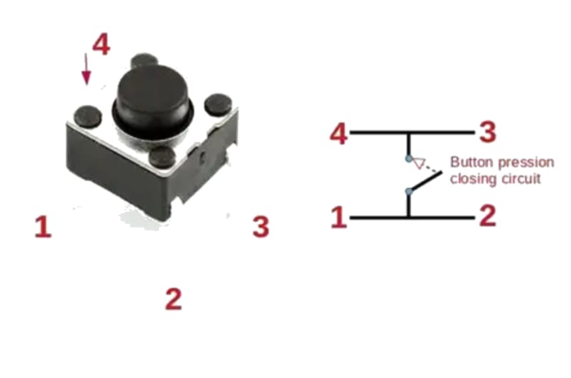
For 4-pin tactile switches, the pins are connected in pairs internally — any pin on one side bridges to any pin on the other side when pressed.
Install necessary Library
No library is required — the button is read with digitalRead(). For debouncing, the built-in millis() timing is sufficient. The Bounce2 library by Thomas O Fredericks provides a more robust debounce solution if needed:
arduino-cli lib install "Bounce2"
Code with complete explanation
This sketch demonstrates reading a push button with debouncing and detecting press, release, hold, and long-press events.
#define BUTTON_PIN  2
#define LED_PIN     13

unsigned long lastDebounceTime = 0;
unsigned long debounceDelay    = 50;  // ms

int lastButtonState = HIGH;   // Previous reading (HIGH = not pressed with pull-up)
int buttonState     = HIGH;   // Current debounced state

unsigned long pressStartTime = 0;
bool isPressed = false;

void setup()
{
  Serial.begin(9600);
  pinMode(BUTTON_PIN, INPUT_PULLUP);
  pinMode(LED_PIN, OUTPUT);
  digitalWrite(LED_PIN, LOW);
}

void loop()
{
  int reading = digitalRead(BUTTON_PIN);

  // Debounce logic
  if (reading != lastButtonState)
  {
    lastDebounceTime = millis();
  }

  if ((millis() - lastDebounceTime) > debounceDelay)
  {
    if (reading != buttonState)
    {
      buttonState = reading;

      if (buttonState == LOW)
      {
        // Button pressed (LOW with pull-up)
        Serial.println("Button PRESSED");
        digitalWrite(LED_PIN, HIGH);
        pressStartTime = millis();
        isPressed = true;
      }
      else
      {
        // Button released
        unsigned long holdDuration = millis() - pressStartTime;
        Serial.print("Button RELEASED after ");
        Serial.print(holdDuration);
        Serial.println(" ms");
        digitalWrite(LED_PIN, LOW);
        isPressed = false;
      }
    }
  }

  // Long-press detection while held
  if (isPressed && (millis() - pressStartTime > 2000))
  {
    Serial.println("Long press detected (> 2 seconds)");
    // Reset timer to avoid repeated messages
    pressStartTime = millis();
  }

  lastButtonState = reading;
}
Using the Bounce2 library
#include <Bounce2.h>

#define BUTTON_PIN 2

Bounce btn = Bounce();

void setup()
{
  Serial.begin(9600);
  btn.attach(BUTTON_PIN, INPUT_PULLUP);
  btn.interval(50);  // Debounce interval in ms
}

void loop()
{
  btn.update();

  if (btn.rose())
  {
    Serial.println("Button released");
  }

  if (btn.fell())
  {
    Serial.println("Button pressed");
  }

  if (btn.currentValue() == LOW)
  {
    // Button is currently held
  }
}
Code breakdown
pinMode(BUTTON_PIN, INPUT_PULLUP)— enables the ATmega’s internal 20–50 kΩ pull-up resistor. The pin reads HIGH when open, LOW when connected to GND.- Debounce algorithm: the reading must remain stable for
debounceDelayms before being accepted as the new state. millis()— returns the number of milliseconds since the Arduino started. Used for non-blocking timing.isPressedflag tracks whether the button is currently held to enable long-press detection.digitalWrite(LED_PIN, HIGH)— turns on the built-in LED while the button is held.
Detecting multiple button states
| State | Condition | Use case |
|---|---|---|
| Pressed | state changed from HIGH → LOW | Trigger an action once |
| Released | state changed from LOW → HIGH | End of button interaction |
| Held | state is LOW for > N ms | Repeat actions |
| Double-click | two presses within a short window | Alternate mode |
Simple toggle (alternative)
bool ledState = false;

void loop()
{
  if (btn.fell())  // Button pressed
  {
    ledState = !ledState;
    digitalWrite(LED_PIN, ledState);
  }
}
Steps to perform this interfacing
- Connect the push button between Arduino digital pin 2 and GND (pull-up configuration).
- No library installation needed.
- Copy the code into the Arduino IDE.
- Select the correct board and port (
Tools > BoardandTools > Port). - Upload the sketch to the Arduino.
- Open the Serial Monitor (
Tools > Serial Monitor, set baud rate to 9600). - Press and release the button — observe the press/release events and hold duration printed.
- Hold the button for > 2 seconds — observe the “Long press” message.
- The built-in LED (pin 13) turns on while the button is held.
Caution
- Internal pull-up range: The ATmega’s internal pull-up resistor is nominally 20 kΩ but varies from 20–50 kΩ between pins and across chips. This is adequate for a simple button but may cause unreliable readings with long wires (> 1 m) due to noise pickup. For long runs, use an external 10 kΩ pull-up resistor and disable
INPUT_PULLUP. - No pull-up / pull-down: Without a pull-up or pull-down resistor, the input pin floats when the button is open, picking up ambient electrical noise. The pin will randomly read HIGH or LOW, causing false triggers. Always use
INPUT_PULLUPor an external resistor. - Inverted logic with pull-up: When using
INPUT_PULLUP, LOW = pressed, HIGH = released. This is the opposite of what beginners often expect. If you need positive logic (HIGH = pressed), use an external pull-down resistor to GND and connect the button between 5V and the pin. - Mechanical bounce: A tactile switch physically bounces for 5–20 ms after contact, producing multiple rapid transitions. Without debouncing, a single press can register as dozens of presses. The debounce delay of 50 ms in the example is conservative — you can reduce it to 10–15 ms for faster response, or increase it to 100 ms for a very bouncy switch (some cheap buttons are worse).
- Schmitt trigger input: The ATmega’s digital inputs include a Schmitt trigger that provides hysteresis (≈ 300 mV). This helps with slow-rising signals but does not eliminate the need for debouncing on mechanical switches.
- 4-pin tactile switch orientation: Many tactile switches have 4 pins arranged in two pairs. The two pins on each side of the switch are electrically connected internally. Pins on opposite sides are connected only when pressed. Use a multimeter in continuity mode to verify the pinout if unsure.