Photoresistor (LDR)
A photoresistor (or light-dependent resistor, LDR) is a passive component whose resistance decreases as incident light intensity increases. It is paired with a fixed resistor to form a voltage divider whose output is read by the Arduino’s ADC. Common applications include automatic night lights, light-activated switches, solar tracking, and ambient light sensing for display brightness.
For this interfacing you need the following components:
- Arduino board (Uno, Nano, Mega, etc.)
- LDR / photoresistor (e.g., GL5528, 5–10 kΩ in bright light, 1 MΩ+ in dark)
- 10 kΩ fixed resistor (for voltage divider)
- Breadboard and jumper wires
- USB cable to connect Arduino to your computer
Schematic
Voltage divider configuration
           5V
            |
           LDR
            |
            +--------- A0 (analog input)
            |
          10 kΩ
            |
           GND
When light is bright, LDR resistance is low (≈ 5–10 kΩ), dividing more voltage to GND, so A0 reads lower. When dark, LDR resistance is high (≥ 1 MΩ), so A0 reads near 5V.
Inverted configuration (optional — higher reading = brighter)
Swap the LDR and the fixed resistor:
           5V
            |
          10 kΩ
            |
            +--------- A0 (analog input)
            |
           LDR
            |
           GND
Now a bright reading gives a higher ADC value. Choose whichever matches your mental model.
Pin Map
| Component | Arduino Pin |
|---|---|
| LDR + fixed resistor junction | A0 |
| Fixed resistor other end | GND |
| LDR other end | 5V |
Install necessary Library
No library is required. The sensor is read with analogRead().
Code with complete explanation
This sketch reads the LDR, converts the value to approximate lux, and triggers an LED at a configurable threshold.
#define LDR_PIN   A0
#define LED_PIN   13

// Voltage divider components
const float R_FIXED = 10000.0;   // 10 kΩ
const float VCC     = 5.0;

void setup()
{
  Serial.begin(9600);
  pinMode(LED_PIN, OUTPUT);
  Serial.println("LDR Light Sensor");
  Serial.println("ADC\tVoltage\t\tResistance\tLux (approx)");
}

void loop()
{
  int adc = analogRead(LDR_PIN);
  float vOut = adc * (VCC / 1023.0);

  // Calculate LDR resistance
  // For circuit: VCC -> LDR -> A0 -> R_fixed -> GND
  // vOut = VCC * R_fixed / (R_ldr + R_fixed)
  // R_ldr = R_fixed * (VCC / vOut - 1)
  float rLdr = R_FIXED * (VCC / vOut - 1.0);

  // Approximate lux using a simple inverse model
  // Typical LDR: R ≈ 10 kΩ @ 100 lux, R ∝ 1 / lux^0.7
  float lux = 100.0 * pow(10000.0 / rLdr, 1.4);

  // Clamp to reasonable range
  if (lux > 10000) lux = 10000;
  if (lux < 0.1)   lux = 0.1;

  Serial.print(adc);
  Serial.print("\t");
  Serial.print(vOut, 4);
  Serial.print(" V\t\t");
  Serial.print(rLdr);
  Serial.print(" Ω\t\t");
  Serial.print(lux, 1);
  Serial.println(" lux");

  // Night-light: turn on LED when dark (< 10 lux)
  if (lux < 10.0)
  {
    digitalWrite(LED_PIN, HIGH);
  }
  else
  {
    digitalWrite(LED_PIN, LOW);
  }

  delay(500);
}
Hysteresis (avoid flickering at threshold)
const float THRESHOLD_ON  = 8.0;   // lux — turn on below this
const float THRESHOLD_OFF = 15.0;  // lux — turn off above this

bool ledState = false;

void loop()
{
  // ... read LDR, calculate lux ...

  if (!ledState && lux < THRESHOLD_ON)
  {
    digitalWrite(LED_PIN, HIGH);
    ledState = true;
  }
  else if (ledState && lux > THRESHOLD_OFF)
  {
    digitalWrite(LED_PIN, LOW);
    ledState = false;
  }
}
Averaging for noise reduction
int readLDR(int samples)
{
  long sum = 0;

  for (int i = 0; i < samples; i++)
  {
    sum += analogRead(LDR_PIN);
    delay(5);
  }

  return sum / samples;
}
Code breakdown
analogRead(A0)— returns 0–1023. For the voltage divider circuit shown, higher ADC = darker (LDR resistance is higher, so less voltage drop across the fixed resistor).- LDR resistance calculation uses the voltage divider formula rearranged. For the second circuit (current-limiting resistor on top), the formula becomes
rLdr = R_FIXED / (VCC / vOut - 1). - Lux conversion is an approximation. Real LDRs have a non-linear R vs lux relationship (log-log slope ≈ 0.7–1.0). The formula
lux = 100 * (10000 / R_ldr)^1.4is an approximation for a typical CdS cell. For accurate lux, calibrate with a known light source and a reference lux meter. - Hysteresis prevents the LED from rapidly flickering when the light level hovers at the threshold.
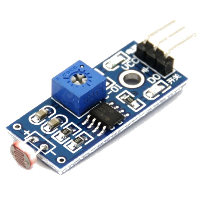
Using as a digital light switch (with threshold pot)
Some LDR modules include a comparator (LM393) and a potentiometer for digital output:
#define LDR_DO 2  // Digital output from LM393 module

void setup()
{
  pinMode(LDR_DO, INPUT);
}

void loop()
{
  if (digitalRead(LDR_DO) == LOW)
  {
    Serial.println("Dark — below threshold");
  }
  else
  {
    Serial.println("Light — above threshold");
  }

  delay(200);
}
Steps to perform this interfacing
- Connect the LDR and 10 kΩ resistor as a voltage divider on the breadboard.
- Connect the junction to the Arduino’s A0 pin.
- No library installation needed.
- Copy the code into the Arduino IDE.
- Select the correct board and port (
Tools > BoardandTools > Port). - Upload the sketch to the Arduino.
- Open the Serial Monitor (
Tools > Serial Monitor, set baud rate to 9600). - Observe the ADC value change when you cover the LDR with your hand vs shining a light on it.
- The built-in LED turns on automatically when the detected lux is below 10.
Caution
- Response time: CdS photoresistors have a slow response time (10–30 ms to fall, 20–50 ms to rise depending on light intensity). This is fine for ambient light sensing but too slow for high-speed optical communication or tachometer applications. For fast light detection, use a photodiode (PIN diode) or a phototransistor.
- Voltage divider resistor selection: The fixed resistor should be chosen to match the LDR’s resistance range. A 10 kΩ resistor gives the best sensitivity around typical room light (100–1000 lux, LDR ≈ 1–10 kΩ). For darker environments, use a 100 kΩ or 1 MΩ pull-up/pull-down. For outdoor use in bright sunlight, use 1–5 kΩ. The formula: choose R_fixed such that the voltage at A0 is ≈ 2.5V (mid-scale ADC) at the light level of greatest interest.
- Lux approximation accuracy: The formula used in the code is an approximation that varies by LDR model. The GL5528 (common in hobby kits) has a typical resistance of ≈ 10 kΩ at 100 lux and ≈ 1 MΩ at 1 lux, with a gamma (γ) of ≈ 0.7–0.8. For accurate lux measurement, characterise the specific LDR at two known light levels and derive the gamma and reference resistance.
- Temperature drift: CdS LDRs exhibit a temperature coefficient of approximately ±0.2–0.5% / °C. This is negligible for most indoor projects (< 10°C temperature variation → < 5% error). For outdoor or high-temperature environments, consider a photodiode with a temperature-compensated amplifier.
- CdS toxicity: CdS (cadmium sulfide) photoresistors contain cadmium, a toxic heavy metal regulated under RoHS in the EU. They should not be used in consumer products sold in the EU. Alternatives: phototransistors (e.g., TEPT5700), ambient light sensors (BH1750, TSL2561), or silicon photodiodes (TEMD6010FX01). For hobby projects, CdS LDRs are still widely available and safe to use if not incinerated or broken open.
- Light spectrum sensitivity: CdS LDRs are most sensitive to green-yellow light (peak ≈ 540 nm). They are less sensitive to blue and red. If your application requires detecting a specific LED colour, verify the LDR’s spectral response or use a photodiode matched to the LED’s wavelength.
- Analog noise: In electrically noisy environments (near motors, relays, switching power supplies), the analog reading can fluctuate by ±10 counts or more. Use the averaging function (
readLDR(N)) and add a 100 nF capacitor from A0 to GND for hardware filtering.