Multiple 7-Segment LED Displays (Multiplexed)
Driving multiple 7-segment displays individually would require 8 pins per digit (7 segments + DP). For N digits, that is 8 × N pins — impractical beyond 2 digits. Multiplexing solves this by connecting all segment pins in parallel and using one common pin per digit. By rapidly switching which digit is active (≈ 1–2 ms per digit), persistence of vision makes all digits appear to be lit simultaneously. The TM1637 (4-digit I²C-like) and MAX7219 (SPI, 8-digit) driver ICs handle multiplexing automatically.
For this interfacing you need the following components:
- Arduino board (Uno, Nano, Mega, etc.)
- 4-digit 7-segment LED display module (common cathode, e.g., 3641BH)
- TM1637 driver module (for 4-digit displays) OR MAX7219 driver IC + 8-digit display
- Breadboard and jumper wires
- USB cable to connect Arduino to your computer
Schematic
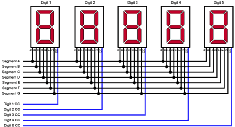
Direct multiplexed wiring (4-digit, no driver IC)
Segment lines (a–g, DP): Arduino Pins 2–9
Digit select (common cathodes): Arduino Pins 10–13 via NPN transistors

                 Arduino
                 -------
Segment a  ----  Pin 2
Segment b  ----  Pin 3
...
Segment g  ----  Pin 8
DP         ----  Pin 9

Digit 1 cathode --[1kΩ]-- 2N2222 Base -- Pin 10
Digit 2 cathode --[1kΩ]-- 2N2222 Base -- Pin 11
Digit 3 cathode --[1kΩ]-- 2N2222 Base -- Pin 12
Digit 4 cathode --[1kΩ]-- 2N2222 Base -- Pin 13
Each digit’s common cathode is driven by an NPN transistor (2N2222) switched by a digital pin. The segment pins drive all four digits in parallel.
TM1637 (4-digit, 2-wire interface) — recommended
TM1637 Module         Arduino
-------------         -------
VCC           -->     5V
GND           -->     GND
CLK           -->     Digital Pin 3
DIO           -->     Digital Pin 2
The TM1637 uses a proprietary 2-wire bus (clock + data) similar to I²C but not compatible.
MAX7219 (8-digit, SPI interface)
MAX7219               Arduino
-------               -------
VCC           -->     5V
GND           -->     GND
DIN           -->     Digital Pin 11 (MOSI)
CS            -->     Digital Pin 10 (SS)
CLK           -->     Digital Pin 13 (SCK)
Pin Map
Direct multiplexed (4-digit, transistor-driven)
| Function | Arduino Pin |
|---|---|
| Segments a–g, DP | 2–9 |
| Digit 1 select | 10 |
| Digit 2 select | 11 |
| Digit 3 select | 12 |
| Digit 4 select | 13 |
TM1637
| Module Pin | Arduino Pin |
|---|---|
| CLK | 3 |
| DIO | 2 |
| VCC | 5V |
| GND | GND |
MAX7219
| Module Pin | Arduino Pin |
|---|---|
| DIN (MOSI) | 11 |
| CS (SS) | 10 |
| CLK (SCK) | 13 |
| VCC | 5V |
| GND | GND |
Install necessary Library
For TM1637
Install TM1637 by Avishay Orpaz (or TM1637Display) via the Library Manager:
arduino-cli lib install "TM1637"
For MAX7219
Install LedControl by Eberhard Fahle via the Library Manager:
arduino-cli lib install "LedControl"
For direct multiplexing
No library required — implement the refresh loop manually.
Code with complete explanation
TM1637 4-digit display
This sketch displays a running count and temperature-like value on a 4-digit 7-segment module.
#include <TM1637Display.h>

#define CLK 3
#define DIO 2

TM1637Display display(CLK, DIO);

void setup()
{
  Serial.begin(9600);
  display.setBrightness(7);  // 0 (min) to 7 (max)

  // Show a test pattern
  display.showNumberDec(8888);
  delay(1000);
  display.clear();
}

void loop()
{
  // Display a count (0–9999)
  static int count = 0;

  display.showNumberDec(count, false);  // leadingZeros = false
  count = (count + 1) % 10000;

  delay(100);
}
TM1637 with colon LEDs and time display
void showTime(int hours, int minutes)
{
  // Show 4 digits with colon between digit 2 and 3
  display.showNumberDecEx(hours * 100 + minutes, 0b01000000, false);

  // The colon is controlled by bit 6 of the second parameter:
  // 0b01000000 = colon ON, 0b00000000 = colon OFF
}

void loop()
{
  showTime(12, 34);
  delay(1000);
  showTime(12, 35);
  delay(1000);
}
Segment-level control (custom characters)
// Segment bit positions (1 = ON):
// -- 0 --
// |     |
// 5     1
// -- 6 --
// |     |
// 4     2
// -- 3 --  .7

// Display "AbCd"
const uint8_t customSegs[] = {
  0b01110111,  // A
  0b01111100,  // b
  0b00111001,  // C
  0b01011110,  // d
};

void loop()
{
  display.setSegments(customSegs, 4, 0);  // data, length, position
  delay(2000);
}
MAX7219 8-digit display
#include <LedControl.h>

#define DIN 11
#define CS  10
#define CLK 13

LedControl lc = LedControl(DIN, CLK, CS, 1);  // 1 module

void setup()
{
  lc.shutdown(0, false);          // Wake up
  lc.setIntensity(0, 8);          // Brightness: 0–15
  lc.clearDisplay(0);             // Clear
}

void loop()
{
  for (int pos = 0; pos < 8; pos++)
  {
    lc.setDigit(0, pos, pos, false);  // addr, digit, value, dp
    delay(200);
  }

  lc.clearDisplay(0);
  delay(500);

  // Show a number
  lc.setChar(0, 0, 'A', false);
  lc.setChar(0, 1, 'b', false);
  lc.setChar(0, 2, 'C', false);
  lc.setChar(0, 3, 'd', false);

  // Or display integer
  lc.setDigit(0, 7, 1, false);
  lc.setDigit(0, 6, 2, false);
  lc.setDigit(0, 5, 3, false);
  lc.setDigit(0, 4, 4, false);
}
Direct multiplexed refresh loop (4-digit manual)
#define NUM_DIGITS 4

// Pin arrays
uint8_t segPins[8]  = {2, 3, 4, 5, 6, 7, 8, 9};
uint8_t digPins[4]  = {10, 11, 12, 13};

// Digits 0–9 patterns (CC)
const uint8_t patterns[10] = {
  0x3F, 0x06, 0x5B, 0x4F, 0x66,
  0x6D, 0x7D, 0x07, 0x7F, 0x6F
};

uint8_t displayBuffer[4] = {1, 2, 3, 4};  // Shows "1234"

void setup()
{
  for (int i = 0; i < 8; i++) pinMode(segPins[i], OUTPUT);
  for (int i = 0; i < 4; i++) pinMode(digPins[i], OUTPUT);
}

void loop()
{
  refreshDisplay();
  // Other code runs here — the display is refreshed in the same loop
}

void refreshDisplay()
{
  for (int d = 0; d < NUM_DIGITS; d++)
  {
    // Turn off all digits
    for (int i = 0; i < NUM_DIGITS; i++)
      digitalWrite(digPins[i], LOW);  // CC: LOW = off

    // Set segment pattern for this digit
    uint8_t pat = patterns[displayBuffer[d]];
    for (int s = 0; s < 8; s++)
      digitalWrite(segPins[s], (pat >> s) & 1);

    // Turn on this digit
    digitalWrite(digPins[d], HIGH);  // CC: HIGH = on

    delay(2);  // 2 ms per digit = 8 ms per cycle = 125 Hz refresh
  }
}
Code breakdown
- TM1637:
display.showNumberDec(value)displays a 4-digit integer. Leading zeros are suppressed by default. The colon is controlled by bit 6 of the second parameter toshowNumberDecEx(). - MAX7219:
lc.setDigit(module, position, value, dp)sets a single digit (0–9) at position 0–7.setChar()accepts hex digits and letters A–F. - Direct multiplexing: The
refreshDisplay()function is called repeatedly inloop(). It iterates through each digit, setting the segment pattern and enabling only that digit’s common cathode. The 2 ms delay per digit gives ≈ 125 Hz refresh — fast enough to avoid flicker. - The segment pattern lookup uses a bitmask approach: bit 0 = segment a, bit 1 = b, … bit 7 = dp. This reduces the data to a single byte per digit.
display.setSegments(raw, len, pos)sends raw segment bytes directly to the TM1637, enabling custom characters like ° (degree symbol for temperature).
Steps to perform this interfacing
- Connect the TM1637 or MAX7219 module to the Arduino as shown.
- Install the appropriate library via the Library Manager.
- Copy the relevant code into the Arduino IDE.
- Select the correct board and port (
Tools > BoardandTools > Port). - Upload the sketch to the Arduino.
- The display will show “8888” (test), then begin counting from 0 to 9999.
- For the TM1637, observe the colon can be toggled for time displays.
- For direct multiplexing, wire the transistors and observe the multiplexed display.
Caution
- Multiplexing timing: The human eye perceives flicker at rates below ≈ 60 Hz. For N digits at refresh rate R, each digit is on for 1/(N × R) seconds. At 4 digits and 100 Hz refresh, each digit is on for 2.5 ms — the segments must be bright enough during this short window to appear continuous. Increase brightness by lowering resistor values or reducing the digit count.
- Transistor drivers for direct multiplex: Never drive the common cathode (or anode) of a multi-digit display directly from an Arduino pin. When all 8 segments are lit, the common pin carries up to 8 × 15 mA = 120 mA — far exceeding the Arduino pin’s 40 mA limit. Always use a transistor (2N2222 or N-channel MOSFET for CC; PNP or P-channel for CA) per digit.
- TM1637 vs MAX7219: The TM1637 drives 4 digits (or 6 in some variants) and does not support daisy-chaining. The MAX7219 drives 8 digits per IC and supports daisy-chaining multiple ICs via SPI for 16, 24, or more digits. For 1–4 digits, TM1637 is simpler (2 wires). For 5+ digits, use MAX7219.
- TM1637 voltage: The TM1637 operates at 5V but its logic inputs are 5V-tolerant. Do not use 3.3V Arduinos without a level shifter — the module may not recognise 3.3V as a logic HIGH. Some modules accept 3.3V on VCC but have reduced brightness.
- MAX7219 capacitor: Place a 10 µF electrolytic capacitor between VCC and GND as close to the MAX7219 as possible. The IC draws current spikes when switching digits; without the capacitor, the voltage dips can cause the display to flicker or the Arduino to reset.
- Decimal point (DP): In multiplexed displays, the DP is one segment (bit 7 in the pattern). It is dimmer than the other segments because it is only on for 1/N of the time (same as all other segments). For always-on DP, a separate pin is required.
- Brightness vs resistor selection: With TM1637/MAX7219, brightness is set in software (
setBrightness()orsetIntensity()). With direct multiplexing, brightness is determined by the series resistors on the segment lines. Lower resistors = brighter segments but higher current. Calculate: R = (V_supply - V_f) / I_seg. For a 5V supply, red LED V_f = 1.8V, desired I = 10 mA (since each segment is on 1/4 of the time, peak current can be higher): R = (5 - 1.8) / 0.01 = 320 Ω → 330 Ω standard.