MPU6050 IMU (Accelerometer + Gyroscope)
The MPU6050 is a 6-axis inertial measurement unit (IMU) combining a 3-axis MEMS accelerometer (±2/±4/±8/±16 g) and a 3-axis MEMS gyroscope (±250/±500/±1000/±2000 °/s) in a single 4 × 4 mm package. It communicates over I²C and includes an onboard Digital Motion Processor (DMP) that can fuse sensor data into quaternion orientation, eliminating the need for external sensor fusion calculations. It also has a 1024-byte FIFO buffer for burst data logging.
For this interfacing you need the following components:
- Arduino board (Uno, Nano, Mega, etc.)
- MPU6050 module (GY-521)
- Breadboard and jumper wires
- USB cable to connect Arduino to your computer
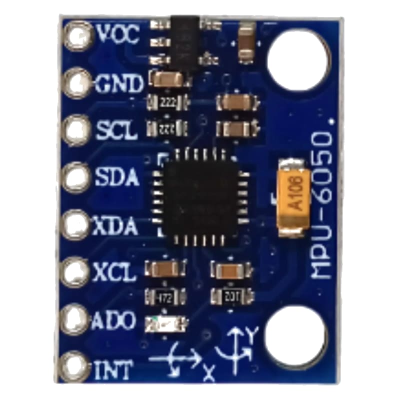
Schematic
I²C wiring
GY-521 Module         Arduino
------------         -------
VCC           -->     5V (module has 3.3V regulator)
GND           -->     GND
SCL           -->     A5 (Uno) / SCL (Mega)
SDA           -->     A4 (Uno) / SDA (Mega)

INT (optional) -->    Digital Pin 2 (interrupt for data-ready)
AD0 pin (I²C address select)
The AD0 pin (pin 9 on the GY-521) selects the I²C address:
- 0x68 — AD0 = LOW (default, GND)
- 0x69 — AD0 = HIGH (VCC)
If you have two MPU6050s, connect one with AD0 to GND (0x68) and one with AD0 to VCC (0x69).
Pin Map
| GY-521 Pin | Name | Arduino Connection |
|---|---|---|
| VCC | Power | 5V |
| GND | Ground | GND |
| SCL | I²C Clock | A5 (Uno), 21 (Mega) |
| SDA | I²C Data | A4 (Uno), 20 (Mega) |
| INT | Interrupt (data-ready) | Pin 2 (optional) |
| XDA | Auxiliary I²C data | (unused) |
| XCL | Auxiliary I²C clock | (unused) |
| AD0 | I²C address select | GND (0x68) or VCC (0x69) |
Install necessary Library
Install the Adafruit MPU6050 library by Adafruit via the Library Manager.
Dependencies: Adafruit BusIO, Adafruit Unified Sensor.
arduino-cli lib install "Adafruit MPU6050"
arduino-cli lib install "Adafruit Unified Sensor"
For DMP-based quaternion output, install the MPU6050 library by Electronic Cats (or the DMP-compatible version by jrowberg/i2cdevlib — manual install from GitHub).
Code with complete explanation
Basic accelerometer + gyroscope (raw values)
#include <Wire.h>
#include <Adafruit_Sensor.h>
#include <Adafruit_MPU6050.h>

Adafruit_MPU6050 mpu;

void setup()
{
  Serial.begin(9600);

  if (!mpu.begin())
  {
    Serial.println("MPU6050 not found!");
    while (1) {}
  }

  // Configure accelerometer range
  mpu.setAccelerometerRange(MPU6050_RANGE_2_G);

  // Configure gyroscope range
  mpu.setGyroRange(MPU6050_RANGE_250_DEG);

  // Configure digital low-pass filter (DLPF)
  mpu.setFilterBandwidth(MPU6050_BAND_21_HZ);

  Serial.println("MPU6050 IMU");
  Serial.println();
}

void loop()
{
  sensors_event_t a, g, temp;
  mpu.getEvent(&a, &g, &temp);

  // Accelerometer (m/s²)
  Serial.print("Accel X: ");
  Serial.print(a.acceleration.x);
  Serial.print("  Y: ");
  Serial.print(a.acceleration.y);
  Serial.print("  Z: ");
  Serial.print(a.acceleration.z);
  Serial.println(" m/s²");

  // Gyroscope (rad/s)
  Serial.print("Gyro  X: ");
  Serial.print(g.gyro.x);
  Serial.print("  Y: ");
  Serial.print(g.gyro.y);
  Serial.print("  Z: ");
  Serial.print(g.gyro.z);
  Serial.println(" rad/s");

  // Temperature
  Serial.print("Temp: ");
  Serial.print(temp.temperature);
  Serial.println(" °C");

  Serial.println();
  delay(200);
}
DMP — quaternion and Euler angles (sensor fusion)
The DMP fuses accelerometer and gyroscope data to produce orientation in quaternion form, eliminating gyroscope drift.
#include <MPU6050_tockn.h>
// Alternative: #include <MPU6050.h> (by Electronic Cats)

MPU6050 mpu6050(Wire);

void setup()
{
  Serial.begin(9600);
  Wire.begin();
  mpu6050.begin();
  mpu6050.calcGyroOffsets(true);  // Auto-calibrate gyro
}

void loop()
{
  mpu6050.update();

  Serial.print("Angle X: ");
  Serial.print(mpu6050.getAngleX());
  Serial.print("°  Y: ");
  Serial.print(mpu6050.getAngleY());
  Serial.print("°  Z: ");
  Serial.print(mpu6050.getAngleZ());
  Serial.println("°");

  delay(50);
}
Motion detection (interrupt-driven)
volatile bool dataReady = false;

void setup()
{
  pinMode(2, INPUT_PULLUP);
  attachInterrupt(digitalPinToInterrupt(2), onDataReady, RISING);
}

void loop()
{
  if (dataReady)
  {
    dataReady = false;
    sensors_event_t a, g, temp;
    mpu.getEvent(&a, &g, &temp);
    // Process data
  }
}

void onDataReady()
{
  dataReady = true;
}
Code breakdown
mpu.getEvent(&a, &g, &temp)— fills threesensors_event_tstructures with accelerometer (m/s²), gyroscope (rad/s), and temperature (°C) data. This is the Adafruit Unified Sensor interface.mpu.setAccelerometerRange(range)— sets the accelerometer full-scale range. ±2 g (default) gives best resolution (0.061 mg/LSB). ±16 g for high-impact applications.mpu.setGyroRange(range)— sets the gyroscope full-scale range. ±250 °/s (default) for slow rotation (best resolution). ±2000 °/s for fast rotation.mpu.setFilterBandwidth(bandwidth)— sets the DLPF (digital low-pass filter) cutoff frequency. Lower bandwidth = less noise, slower response. Options: 5, 10, 21, 44, 94, 184, 260 Hz. 21 Hz is a good balance.- DMP-based angles from the
MPU6050_tocknlibrary provide drift-free orientation by fusing accelerometer (long-term reference) with gyroscope (short-term dynamics). mpu6050.calcGyroOffsets(true)— auto-calibrates the gyroscope bias while the sensor is stationary. Withtrue, prints calibration progress. The gyroscope can be configured (settrue/falseto enable/disable the auto-calibration print) by the respective library.
Step counter (pedometer)
// Many MPU6050 libraries support step counting via DMP
// This pseudocode illustrates the concept:

void setup()
{
  mpu6050.begin();
  mpu6050.enableStepCounter();
}

void loop()
{
  mpu6050.update();

  if (mpu6050.stepDetected())
  {
    Serial.print("Steps: ");
    Serial.println(mpu6050.getStepCount());
  }
}
Steps to perform this interfacing
- Connect the MPU6050 (GY-521) to the Arduino as shown.
- Install the Adafruit MPU6050 library and Adafruit Unified Sensor.
- Copy the code into the Arduino IDE.
- Select the correct board and port (
Tools > BoardandTools > Port). - Upload the sketch to the Arduino.
- Open the Serial Monitor (
Tools > Serial Monitor, set baud rate to 9600). - Hold the sensor flat and still — observe the accelerometer values: Z ≈ 9.81 m/s², X and Y ≈ 0.
- Rotate the sensor — observe the gyroscope values change proportional to rotation speed.
- Tilt the sensor and hold — the accelerometer shows the static tilt angle while the gyroscope returns to near 0 (when not moving).
- With the DMP code, the angle values integrate gyroscope data and auto-correct from the accelerometer.
Caution
- Gyroscope drift: The gyroscope has a zero-rate bias (offset) that varies with temperature and from unit to unit. When the sensor is stationary, the gyroscope output is not zero — it may read 0.5–5 °/s on each axis even when not moving. Gyroscope calibration is essential for any application. The
calcGyroOffsets()function samples the gyroscope for ≈ 2 seconds while the sensor is stationary and stores the average bias. This bias is then subtracted from all subsequent readings. Recalibrate when the temperature changes by > 5°C. - Accelerometer bandwidth vs noise: The default DLPF bandwidth (260 Hz) allows high-frequency noise through. The accelerometer output will appear noisy (fluctuations of ±0.3 m/s² or more). Decreasing the bandwidth to 21 Hz or lower reduces noise significantly but adds ≈ 10 ms of group delay. For tilt sensing (static orientation), use ≤ 21 Hz. For impact detection, use ≥ 94 Hz.
- DMP quaternion accuracy: The DMP provides Euler angles (roll, pitch, yaw) by fusing accelerometer and gyroscope data. Pitch and roll are accurate to ≈ 1° after calibration. Yaw (heading) will drift over minutes because the MPU6050 has no magnetometer — it cannot sense absolute heading. Yaw drift is typically 1–5°/minute. For drift-free yaw, add a magnetometer (HMC5883L or AK8963) and fuse with a 9-axis algorithm (AHRS). The MPU6050 has an auxiliary I²C bus (XDA/XCL) that can interface directly with a magnetometer without using the Arduino.
- 3.3V logic: The MPU6050 operates at 3.3V. The GY-521 breakout includes a 3.3V regulator and level shifters for 5V I²C, so you can safely connect VCC to 5V. The INT pin outputs 3.3V — recognised as HIGH by the Arduino’s 5V input. If using a bare MPU6050 without a breakout, power from 3.3V and use a level shifter on I²C.
- FIFO overflow: At high output rates (1 kHz) with all axes enabled, the 1024-byte FIFO buffer fills in ≈ 170 ms. If the Arduino does not read the FIFO frequently enough, data is lost. Use the data-ready interrupt (INT pin) to trigger reads, or use the DMP which manages the FIFO internally at ≈ 200 Hz.
- Self-heating: The MPU6050’s internal temperature sensor reads approximately 30–45°C during operation — 5–15°C above ambient due to self-heating from the IC. The gyroscope bias drifts with temperature, which is why the chip includes a temperature sensor (for bias compensation in the DMP). In still air, the sensor runs warmer than in forced airflow. Mount the sensor with an air gap underneath the PCB to reduce heat build-up.
- Mounting vibration: MEMS gyroscopes are sensitive to vibration. When mounted on a motorised platform (drone, robot), the vibration couples into the gyroscope, causing angle drift. Use soft silicone mounts (the GY-521 does not come with them — you must add them). Rubber grommets or double-sided foam tape reduces vibration coupling at high frequencies.
- I²C bus speed: The MPU6050 supports up to 400 kHz (Fast Mode) I²C. The Arduino Wire library defaults to 100 kHz. At 400 kHz, data can be read at 1 kHz sample rate without saturating the bus. Set
Wire.setClock(400000)insetup()for faster sampling.