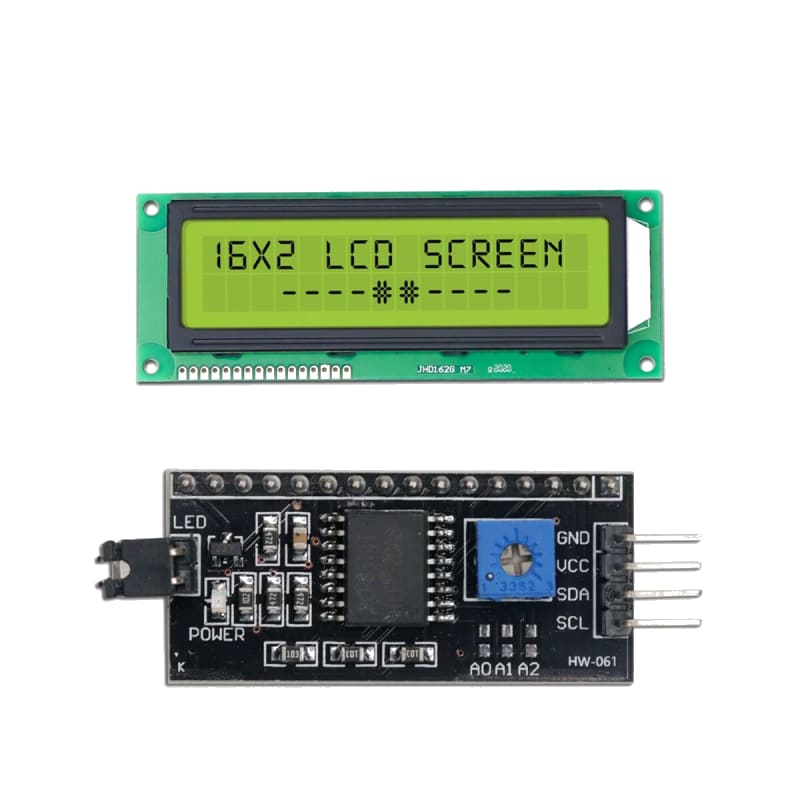
LCD 16×2 Display (HD44780)
The HD44780 is a de-facto standard controller for alphanumeric character LCDs (16×2, 20×4, etc.). It uses a parallel interface (4-bit or 8-bit data bus + 3 control lines) and can display standard ASCII characters plus custom 5×8 pixel glyphs. The I²C backpack (PCF8574) reduces the wiring to just 2 data lines (SDA, SCL) plus power. These displays are widely used for sensor readouts, menu systems, and status displays.
For this interfacing you need the following components:
- Arduino board (Uno, Nano, Mega, etc.)
- 16×2 character LCD (HD44780-compatible)
- Breadboard and jumper wires
- 10 kΩ potentiometer (contrast adjustment)
- USB cable to connect Arduino to your computer
- (Optional) I²C LCD backpack module (PCF8574)
Schematic
4-bit parallel mode (6 Arduino pins)
LCD Pin            Arduino
-------            -------
1 (VSS / GND)  --  GND
2 (VDD / VCC)  --  5V
3 (V0 / Contrast)  Centre pin of 10k pot
   Pot ends to 5V and GND
4 (RS)         --  Digital Pin 12
5 (RW)         --  GND (write-only, no read needed)
6 (E)          --  Digital Pin 11
11 (D4)        --  Digital Pin 5
12 (D5)        --  Digital Pin 4
13 (D6)        --  Digital Pin 3
14 (D7)        --  Digital Pin 2
15 (A / LED+)  --  5V via 100 Ω resistor
16 (K / LED-)  --  GND
I²C backpack (2 Arduino pins) — recommended
I²C Backpack          Arduino
------------          -------
VCC           -->     5V
GND           -->     GND
SDA           -->     A4 (Uno) / SDA (Mega)
SCL           -->     A5 (Uno) / SCL (Mega)
The I²C address is typically 0x27 or 0x3F. Use an I²C scanner sketch to confirm.
Pin Map
Parallel (4-bit mode)
| LCD Pin | Name | Arduino Pin |
|---|---|---|
| 1 | VSS (GND) | GND |
| 2 | VDD (5V) | 5V |
| 3 | V0 (Contrast) | 10 kΩ pot wiper |
| 4 | RS (Register Select) | 12 |
| 5 | RW (Read/Write) | GND |
| 6 | E (Enable) | 11 |
| 11 | D4 (Data bit 4) | 5 |
| 12 | D5 (Data bit 5) | 4 |
| 13 | D6 (Data bit 6) | 3 |
| 14 | D7 (Data bit 7) | 2 |
| 15 | A (Backlight anode) | 5V via 100 Ω |
| 16 | K (Backlight cathode) | GND |
I²C backpack
| Module Pin | Arduino Pin |
|---|---|
| VCC | 5V |
| GND | GND |
| SDA | A4 (Uno), 20 (Mega) |
| SCL | A5 (Uno), 21 (Mega) |
Install necessary Library
For parallel mode
Use the built-in LiquidCrystal library (included with the Arduino IDE).
For I²C backpack
Install LiquidCrystal I2C by Frank de Brabander (or LiquidCrystal I2C by Marco Schwartz) via the Library Manager:
arduino-cli lib install "LiquidCrystal I2C"
Code with complete explanation
I²C mode (simpler wiring)
This sketch displays sensor-like data on the LCD with custom characters.
#include <LiquidCrystal_I2C.h>

// Address 0x27 or 0x3F, 16 columns, 2 rows
LiquidCrystal_I2C lcd(0x27, 16, 2);

// Custom character: degree symbol (°) — 5×8 pixel
byte degreeChar[8] = {
  0b00110,
  0b01001,
  0b01001,
  0b00110,
  0b00000,
  0b00000,
  0b00000,
  0b00000,
};

void setup()
{
  lcd.init();          // Initialise the LCD
  lcd.backlight();     // Turn on backlight

  // Create custom characters
  lcd.createChar(0, degreeChar);  // Index 0

  lcd.setCursor(0, 0);
  lcd.print("LCD 16x2 Ready");

  lcd.setCursor(0, 1);
  lcd.print("Temp: 22");
  lcd.write(byte(0));  // Display °
  lcd.print("C");
}

void loop()
{
  // Scroll text on row 1
  static int offset = 0;
  char msg[] = "Scrolling text demo... ";

  lcd.setCursor(0, 1);

  for (int i = 0; i < 16; i++)
  {
    lcd.print(msg[(offset + i) % strlen(msg)]);
  }

  offset = (offset + 1) % strlen(msg);
  delay(300);
}
Parallel mode (4-bit)
#include <LiquidCrystal.h>

LiquidCrystal lcd(12, 11, 5, 4, 3, 2);  // RS, E, D4, D5, D6, D7

void setup()
{
  lcd.begin(16, 2);
  lcd.print("Hello, World!");
}

void loop()
{
  lcd.setCursor(0, 1);
  lcd.print(millis() / 1000);
  lcd.print(" seconds");
  delay(1000);
}
Custom characters and animations
// Heart bitmap
byte heart[8] = {
  0b00000,
  0b01010,
  0b11111,
  0b11111,
  0b11111,
  0b01110,
  0b00100,
  0b00000,
};

// Charging battery animation
byte battery[3][8] = {
  {  // 0% empty
    0b01110,
    0b10001,
    0b10001,
    0b10001,
    0b10001,
    0b10001,
    0b11111,
  },
  {  // 50% half
    0b01110,
    0b10001,
    0b11111,
    0b11111,
    0b10001,
    0b10001,
    0b11111,
  },
  {  // 100% full
    0b01110,
    0b11111,
    0b11111,
    0b11111,
    0b11111,
    0b11111,
    0b11111,
  },
};

void setup()
{
  lcd.createChar(0, heart);
  lcd.createChar(1, battery[0]);
  lcd.createChar(2, battery[1]);
  lcd.createChar(3, battery[2]);

  lcd.write(byte(0));           // Heart
  lcd.print(" Welcome!");
}

void loop()
{
  // Animate battery
  lcd.setCursor(0, 1);

  for (int frame = 0; frame < 3; frame++)
  {
    lcd.write(byte(1 + frame));  // Display battery frame
    delay(500);
  }
}
Code breakdown
LiquidCrystal_I2C lcd(addr, cols, rows)— creates an LCD object at the given I²C address with the specified dimensions.lcd.init()— initialises the LCD (for I²C). For parallel:lcd.begin(cols, rows)in the constructor.lcd.backlight()/lcd.noBacklight()— turn the backlight on/off (I²C only).lcd.setCursor(col, row)— positions the cursor. Row 0 is the top line (0-indexed).lcd.print(text)— prints text at the current cursor position.lcd.write(byte(n))— writes a custom character stored at index n (0–7).lcd.createChar(index, bitmap)— stores a custom 5×8 pixel character bitmap (8 bytes) at the given index. Maximum 8 custom characters.lcd.clear()— clears the screen and moves cursor home.lcd.scrollDisplayRight()/lcd.scrollDisplayLeft()— scrolls the content by one column.lcd.autoscroll()/lcd.noAutoscroll()— toggles automatic scrolling.
Controlling cursor and display
lcd.cursor();       // Show underline cursor
lcd.noCursor();     // Hide cursor
lcd.blink();        // Show blinking block cursor
lcd.noBlink();      // Hide blinking cursor
lcd.display();      // Turn display on (data preserved)
lcd.noDisplay();    // Turn display off (data preserved)
Steps to perform this interfacing
- For parallel LCD: Connect the LCD as shown in the 4-bit schematic. Adjust the 10 kΩ potentiometer for clear contrast.
- For I²C LCD: Connect only VCC, GND, SDA, SCL to the Arduino. Determine the I²C address (0x27 or 0x3F) using an I²C scanner sketch if unsure.
- Install the appropriate library (LiquidCrystal for parallel, LiquidCrystal I2C for I²C).
- Copy the code into the Arduino IDE.
- Select the correct board and port (
Tools > BoardandTools > Port). - Upload the sketch to the Arduino.
- The top row shows “LCD 16x2 Ready” and the bottom row shows “Temp: 22°C”.
- The bottom row scrolls text with animation.
Caution
- Contrast potentiometer is essential: Without the 10 kΩ pot on pin 3 (V0), the display will either show nothing (too high contrast — all pixels dark) or be invisible (too low contrast — no pixels visible). Adjust it while the Arduino is running until the characters are sharp. Set the pot to minimum resistance (wiper to GND) as a starting point and increase slowly.
- 5V only: Standard HD44780 LCDs require 5V logic. Do not use with 3.3V Arduino boards (Due, Zero, MKR) without a level shifter — the LCD’s VIH minimum is ≈ 2.7V but the internal timing may fail at 3.3V. For 3.3V operation, look for “3.3V LCD” modules (often with a boost converter for the LCD drive).
- Backlight resistor: Most LCDs have a backlight rated for 20–50 mA. The backlight is an LED with an internal resistor on some modules, but many require an external resistor. A 100 Ω series resistor from 5V to pin 15 limits current to ≈ 20–30 mA. If the backlight is too bright or flickers, increase the resistor. If it’s too dim, check whether the module has an onboard resistor (some do — adding another will make it dimmer).
- I²C address conflict: The PCF8574 I²C backpack typically uses address 0x27 (A0/A1/A2 = HIGH) or 0x3F (address with different A-pin settings). If you have multiple I²C devices, ensure no address collision. Solder bridges on the backpack can change the address (0x20–0x27 range).
- 4-bit vs 8-bit mode: The HD44780 supports 4-bit and 8-bit data bus modes. The 8-bit mode uses pins D0–D7 (4 extra pins) and is faster but offers no practical advantage on an Arduino running at 16 MHz. 4-bit mode is sufficient for most applications.
- Read/Write pin (RW): The RW pin determines whether the LCD reads from or writes to the data bus. By connecting RW to GND, the LCD is permanently in write mode. This is safe for the LiquidCrystal library, which does not read the LCD’s busy flag (it uses fixed delays instead). If you ever switch to a library that reads the busy flag, connect RW to an Arduino pin.
- 3.3V vs 5V contrast: On 3.3V Arduinos, the LCD’s contrast voltage (pin 3) should be between 0V and 3.3V. Using a 5V pot wiper will overdrive the contrast input. Connect the pot between 3.3V and GND instead.