Laser Emitter Module (KY-008)
The KY-008 laser emitter module contains a small 650 nm red laser diode (Class 1 / Class 2, < 5 mW) with a built-in current-limiting resistor and a 5V-compatible transistor driver. It draws approximately 25–35 mA from a 5V supply. The laser can be modulated with PWM for brightness control or used for simple ON/OFF switching. Applications include laser tripwires (security alarms), laser pointers, laser show effects, and optical communication.
For this interfacing you need the following components:
- Arduino board (Uno, Nano, Mega, etc.)
- KY-008 laser emitter module (or similar 5V laser diode module)
- Breadboard and jumper wires
- USB cable to connect Arduino to your computer
- (Optional) LDR / photoresistor or photodiode for receiver
Schematic
KY-008 Module Arduino
------------- -------
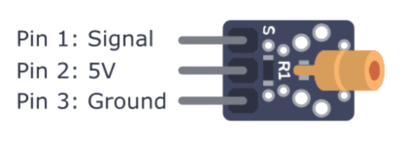
S (Signal) --> Digital Pin 9 (PWM-capable)
VCC --> 5V
GND --> GND
The module is active HIGH — applying a HIGH signal (5V) to the S pin turns on the laser. A LOW signal turns it off.
Pin Map
| Module Pin | Name | Arduino Connection |
|---|---|---|
| S | Signal (ON/OFF or PWM) | Pin 9 |
| VCC | Power | 5V |
| GND | Ground | GND |
Install necessary Library
No library is required. The laser is controlled with digitalWrite() or analogWrite().
Code with complete explanation
This sketch demonstrates ON/OFF control, PWM brightness modulation, Morse code transmission, and an optical tripwire alarm.
#define LASER_PIN 9

void setup()
{
  Serial.begin(9600);
  pinMode(LASER_PIN, OUTPUT);
  digitalWrite(LASER_PIN, LOW);

  Serial.println("Laser Emitter Control");
  Serial.println("Commands:");
  Serial.println("  O — Laser ON");
  Serial.println("  F — Laser OFF");
  Serial.println("  B — Blink 3x");
  Serial.println("  M — Send Morse (SOS)");
  Serial.println("  P — Pulse mode");
}

void loop()
{
  if (Serial.available())
  {
    char cmd = Serial.read();

    switch (cmd)
    {
      case 'O':
        digitalWrite(LASER_PIN, HIGH);
        Serial.println("Laser ON");
        break;

      case 'F':
        digitalWrite(LASER_PIN, LOW);
        Serial.println("Laser OFF");
        break;

      case 'B':
        blinkLaser(3, 200);
        break;

      case 'M':
        sendMorseSOS();
        break;

      case 'P':
        pulseLaser();
        break;
    }
  }
}

void blinkLaser(int times, int ms)
{
  for (int i = 0; i < times; i++)
  {
    digitalWrite(LASER_PIN, HIGH);
    delay(ms);
    digitalWrite(LASER_PIN, LOW);
    delay(ms);
  }
}

void sendMorseSOS()
{
  // S = dot-dot-dot, O = dash-dash-dash
  // dot = 200 ms, dash = 600 ms, intra-char gap = 200 ms

  for (int i = 0; i < 3; i++)  // S
  {
    digitalWrite(LASER_PIN, HIGH);
    delay(200);
    digitalWrite(LASER_PIN, LOW);
    delay(200);
  }

  delay(400);  // Inter-letter gap

  for (int i = 0; i < 3; i++)  // O
  {
    digitalWrite(LASER_PIN, HIGH);
    delay(600);
    digitalWrite(LASER_PIN, LOW);
    delay(200);
  }

  delay(400);

  for (int i = 0; i < 3; i++)  // S
  {
    digitalWrite(LASER_PIN, HIGH);
    delay(200);
    digitalWrite(LASER_PIN, LOW);
    delay(200);
  }

  Serial.println("SOS sent");
}

void pulseLaser()
{
  // PWM fade effect
  for (int i = 0; i <= 255; i++)
  {
    analogWrite(LASER_PIN, i);
    delay(3);
  }

  for (int i = 255; i >= 0; i--)
  {
    analogWrite(LASER_PIN, i);
    delay(3);
  }
}
Laser tripwire (with LDR receiver)
int ldrPin = A0;     // LDR voltage divider input

void setup()
{
  Serial.begin(9600);
  pinMode(LASER_PIN, OUTPUT);
  digitalWrite(LASER_PIN, HIGH);  // Laser always on
}

void loop()
{
  int light = analogRead(ldrPin);

  // LDR reading when laser is on target ≈ 800–950
  // LDR reading when beam is broken  ≈ 100–300
  if (light < 500)
  {
    Serial.println("TRIP! Beam broken");
    digitalWrite(LASER_PIN, LOW);  // Turn off laser
    delay(2000);                   // Cooldown
    digitalWrite(LASER_PIN, HIGH); // Re-arm
  }
  delay(50);
}
Code breakdown
digitalWrite(LASER_PIN, HIGH)— turns the laser on by applying 5V to the module’s signal pin. The module’s onboard transistor switches the laser diode.analogWrite(LASER_PIN, value)— applies a PWM signal to modulate the laser intensity. At low duty cycles (< 30), the laser may not emit visible light (the diode has a threshold current below which no lasing occurs).blinkLaser(times, ms)— flashes the laser at a fixed interval.- Morse SOS: three short (dot = 200 ms), three long (dash = 600 ms), three short — a standard distress signal.
- The tripwire uses an LDR (light-dependent resistor) in a voltage divider. When the laser beam is pointed directly at the LDR, the resistance is low and the analog reading is high. When the beam is broken, ambient light is much dimmer and the ADC reading drops.
PWM modulation for optical communication
// Transmitter: send binary data by modulating laser
void sendByte(uint8_t data)
{
  for (int bit = 0; bit < 8; bit++)
  {
    if (data & (1 << bit))
    {
      analogWrite(LASER_PIN, 255);  // HIGH = 1
    }
    else
    {
      analogWrite(LASER_PIN, 50);   // LOW (barely visible) = 0
    }

    delay(5);
  }

  analogWrite(LASER_PIN, 0);  // End byte
  delay(10);
}
Steps to perform this interfacing
- Connect the KY-008 laser module to the Arduino as shown in the schematic.
- No library installation needed.
- Copy the code into the Arduino IDE.
- Select the correct board and port (
Tools > BoardandTools > Port). - Upload the sketch to the Arduino.
- Open the Serial Monitor (
Tools > Serial Monitor, set baud rate to 9600). - Type O to turn the laser on — a red dot appears.
- Type F to turn the laser off.
- Type B to blink the laser three times.
- Type M to send SOS in Morse code.
- Type P to see a PWM fade effect.
- Never point the laser at eyes or reflective surfaces.
Caution
- ⚠️ EYE SAFETY — LASER RADIATION: The KY-008 is a Class 2 laser (< 1 mW, 650 nm) which is generally considered safe for accidental exposure (blink reflex protects the eye). However, direct exposure to the beam can cause temporary flash blindness and staring into the beam may cause retinal damage. Never aim the laser at a person’s eyes, animals, or reflective surfaces (mirrors, glass, polished metal) that could redirect the beam. The risk is cumulative — even brief exposure should be avoided. For classroom or public use, use a Class 1 laser module with < 0.4 mW output.
- Current draw: The KY-008 draws approximately 25–35 mA when active. The module includes a current-limiting resistor for the laser diode, so no additional resistor is needed. The Arduino 5V pin can supply this comfortably. However, if the laser is left on continuously for extended periods, the module’s surface-mount transistor may warm up. Limit continuous ON time to < 5 minutes and allow a cool-down period.
- Laser diode lifetime: The KY-008 uses a cheap laser diode with a typical lifetime of 2,000–5,000 hours. Continuous operation reduces lifetime; the diode’s light output gradually decreases. PWM dimming (lower duty cycles) extends the diode’s life. Do not exceed the rated supply voltage (5V).
- Heat dissipation: The module has no heatsink. In a sealed enclosure without airflow, the transistor and laser diode can overheat if the laser is on continuously. Use PWM to reduce average power, or pulse the laser (duty cycle < 50%) for long-running applications.
- Class 1 vs Class 2 classification: A Class 1 laser is safe under all conditions (enclosed devices like DVD players). Class 2 (< 1 mW visible) is safe for accidental exposure due to the blink reflex. The KY-008 is typically Class 2, but some modules labelled “5 mW” may exceed 1 mW and be Class 3A — which is hazardous. If unsure, measure the power output with a calibrated laser power meter.
- Optical tripwire limitations: The LDR-based receiver is affected by ambient light. Direct sunlight or bright indoor lighting can saturate the LDR, making it impossible to detect the laser beam. Use a modulated laser (PWM at a specific frequency, e.g., 1 kHz) with a bandpass photodiode receiver circuit for sunlight immunity. A simple LDR works reliably only in dim-to-moderate indoor light.
- Laser divergence: The KY-008’s beam has a divergence angle of approximately 1–2 milliradians. At 10 m, the spot diameter is ≈ 2 cm. At 50 m, it is ≈ 10 cm. For long-distance tripwires, use a collimating lens to reduce divergence, or increase the LDR’s collection area with a lens or reflector.
- Legal restrictions: In many jurisdictions, laser pointers above 5 mW are restricted or require a licence. The KY-008 is generally below this threshold, but check local regulations (FDA 21 CFR 1040 in the US, EN 60825 in the EU). Never use a laser module to deliberately shine at aircraft, vehicles, or people.