INA219 Current Sensor
The INA219 is a high-precision digital current and power monitoring IC from Texas Instruments. It measures both the voltage across a shunt resistor (current) and the bus voltage (load voltage) using a 12-bit ADC, and communicates the results over I2C. It can measure bus voltages up to 26 VDC and currents up to ±3.2 A (depending on the shunt resistor value). The high accuracy (±0.5% typical) and low offset make it ideal for battery monitoring, solar power tracking, and energy metering in IoT devices.
For this interfacing you need the following components:
- Arduino board (Uno, Nano, Mega, etc.)
- INA219 current sensor module (e.g., Adafruit INA219 breakout)
- Breadboard and jumper wires
- USB cable to connect Arduino to your computer
- Power source and load for testing
Schematic
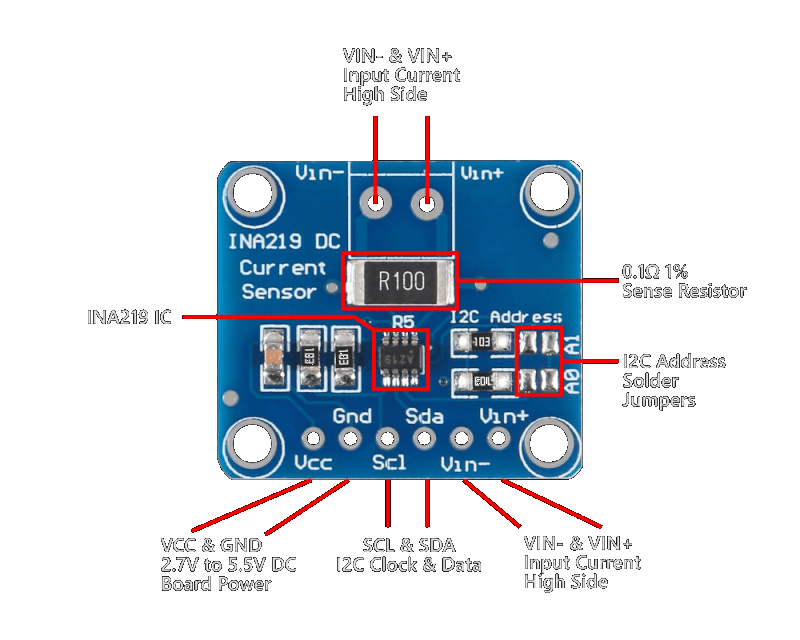
The INA219 communicates over I2C. Connect it to the Arduino as follows:
INA219 Module         Arduino
-------------         -------
VCC           -->     5V (or 3.3V)
GND           -->     GND
SCL           -->     A5 (Uno/Nano) or SCL (Mega)
SDA           -->     A4 (Uno/Nano) or SDA (Mega)

Load circuit:
Power supply (+) --> VIN+ (INA219)
VIN- (INA219)   --> Load (+)
Load (-)        --> Power supply (-)
The INA219 measures current by sensing the voltage drop across its internal (or external) shunt resistor placed in series with the load. The module provides VIN+ and VIN- screw terminals for the series connection.
Pin Map
| Module Pin | Name | Arduino Connection |
|---|---|---|
| VCC | Power | 5V or 3.3V |
| GND | Ground | GND |
| SCL | I2C Clock | A5 (Uno/Nano), SCL (Mega) |
| SDA | I2C Data | A4 (Uno/Nano), SDA (Mega) |
| VIN+ | Load supply input | Power supply (+) |
| VIN- | Load supply output | Load (+) |
I2C pins vary by Arduino board:
- Uno / Nano / Mini: SDA → A4, SCL → A5
- Mega 2560: SDA → 20, SCL → 21
- Leonardo: SDA → 2, SCL → 3
I2C address selection
| A0 | A1 | Address |
|---|---|---|
| GND | GND | 0x40 (default) |
| GND | VCC | 0x41 |
| VCC | GND | 0x44 |
| VCC | VCC | 0x45 |
Install necessary Library
Install the Adafruit INA219 library by Adafruit via the Library Manager (Tools > Manage Libraries).
Alternatively, using arduino-cli:
arduino-cli lib install "Adafruit INA219"
The library depends on the Wire library (built into Arduino IDE).
Code with complete explanation
This sketch reads the bus voltage, shunt voltage, current, and power from the INA219 and prints them to the Serial Monitor.
#include <Wire.h>
#include <Adafruit_INA219.h>

Adafruit_INA219 ina219;

void setup()
{
  Serial.begin(9600);

  if (!ina219.begin())
  {
    Serial.println("INA219 not found. Check wiring.");
    while (1) {}
  }

  // Optional: configure the INA219 for different ranges
  // ina219.setCalibration_32V_2A();  // 32V, ±2A (default)
  // ina219.setCalibration_32V_1A();  // 32V, ±1A (higher resolution)
  // ina219.setCalibration_16V_400mA(); // 16V, ±400mA (highest resolution)

  Serial.println("INA219 Current Sensor Test");
  Serial.println();
}

void loop()
{
  float shuntVoltage  = ina219.getShuntVoltage_mV();
  float busVoltage    = ina219.getBusVoltage_V();
  float current       = ina219.getCurrent_mA();
  float power         = ina219.getPower_mW();
  float loadVoltage   = busVoltage + (shuntVoltage / 1000.0);

  Serial.print("Bus Voltage:   ");
  Serial.print(busVoltage, 3);
  Serial.println(" V");

  Serial.print("Shunt Voltage: ");
  Serial.print(shuntVoltage, 3);
  Serial.println(" mV");

  Serial.print("Load Voltage:  ");
  Serial.print(loadVoltage, 3);
  Serial.println(" V");

  Serial.print("Current:       ");
  Serial.print(current, 1);
  Serial.println(" mA");

  Serial.print("Power:         ");
  Serial.print(power, 1);
  Serial.println(" mW");

  Serial.println();
  delay(1000);
}
Code breakdown
#include <Adafruit_INA219.h>— includes the Adafruit INA219 library.Adafruit_INA219 ina219— creates an INA219 object. Optionally pass the I2C address:Adafruit_INA219 ina219(0x41).ina219.begin()— initialises the sensor. Returnsfalseif no INA219 is detected on the I2C bus.ina219.getShuntVoltage_mV()— returns the voltage drop across the shunt resistor in millivolts. Positive means current flows from VIN+ to VIN-.ina219.getBusVoltage_V()— returns the voltage at VIN- relative to GND (the bus/load voltage).ina219.getCurrent_mA()— returns the current through the shunt in milliamps. Positive = current flowing from VIN+ to VIN-.ina219.getPower_mW()— returns the power (bus voltage × current) in milliwatts.loadVoltage = busVoltage + (shuntVoltage / 1000.0)— the actual voltage at the load = voltage at VIN- plus the small drop across the shunt.
Calibration modes
| Mode | Max Voltage | Max Current | Resolution |
|---|---|---|---|
setCalibration_32V_2A() | 32 V | ±2 A | 0.1 mA (default) |
setCalibration_32V_1A() | 32 V | ±1 A | 0.04 mA |
setCalibration_16V_400mA() | 16 V | ±400 mA | 0.01 mA |
Higher resolution modes limit the max measurable current but provide finer granularity.
Using a custom shunt resistor
If your INA219 module uses a shunt value other than the default 0.1 Ω:
Adafruit_INA219 ina219(0x40);

void setup()
{
  ina219.begin();
  // Custom calibration: max expected current, shunt value
  ina219.setCalibration(5, 0.05); // 5A max, 0.05 Ω shunt
}
Steps to perform this interfacing
- Connect the INA219 module to the Arduino via I2C as shown in the schematic.
- Place the INA219 in series with your load between the power supply and the load: power supply (+) to VIN+, VIN- to load (+), load (-) to power supply GND.
- Install the Adafruit INA219 library via the Library Manager.
- Copy the code into the Arduino IDE.
- Select the correct board and port (
Tools > BoardandTools > Port). - Upload the sketch to the Arduino.
- Open the Serial Monitor (
Tools > Serial Monitor, set baud rate to 9600). - Observe the bus voltage, shunt voltage, current, and power readings. With no load, the current should read approximately 0 mA (with small offset).
- Connect a load (e.g., a resistor or LED) and observe the current and power increase.
Caution
- Maximum voltage: The INA219 bus voltage measurement range is 0–26 VDC. Applying more than 26 V to VIN+ or VIN- will damage the IC. The differential voltage across VIN+ and VIN- must not exceed ±320 mV (the shunt voltage range).
- Shunt resistor: Most INA219 breakout boards use a 0.1 Ω, 2 W shunt resistor. This limits continuous current to approximately ±3.2 A (P = I²R = 3.2² × 0.1 ≈ 1 W safely). For higher currents, replace the shunt with a lower-value resistor and recalibrate using
setCalibration(). For lower currents, a higher-value shunt improves resolution. - Common ground: The INA219 GND must be connected to the power supply GND and the Arduino GND. The INA219 measures voltage relative to its own GND pin — if grounds are not shared, readings will be incorrect.
- Supply voltage for the INA219: The INA219 IC operates from 3.0 V to 5.5 V on VCC. The module can measure bus voltages up to 26 V regardless of VCC (the bus voltage is divided internally). This means you can monitor a 12 V battery while powering the INA219 from the Arduino’s 3.3 V or 5 V pin.
- Inductive loads: The INA219 is designed for DC measurements. Measuring current through inductive loads (motors, solenoids, relays) may produce noisy readings due to PWM switching or back-EMF. Add a 10 µF capacitor across VIN+ and VIN- near the module to filter noise.
- Reverse polarity: Applying reverse voltage across VIN+ and VIN- (VIN- > VIN+ by more than 320 mV) will damage the IC. The INA219 is not reverse-polarity protected. Add a Schottky diode in series with the supply if reverse polarity is possible.