ESP8266/ESP32 – Wi-Fi Communication with Arduino
The ESP8266 and ESP32 are powerful Wi-Fi SoCs from Espressif that can be used as Wi-Fi co-processors with an Arduino. Communicating over serial UART using AT commands, the Arduino offloads Wi-Fi connectivity to the ESP module. The ESP8266 offers 802.11 b/g/n Wi-Fi, while the ESP32 adds Bluetooth, dual-core processing, and more GPIOs. This configuration is useful when you want to add Wi-Fi to an existing Arduino project without rewriting the firmware.
For this interfacing you need the following components:
- Arduino board (Uno, Nano, Mega, etc.)
- ESP8266 module (ESP-01, NodeMCU, or Wemos D1) or ESP32 module
- 3.3V voltage regulator (if using an ESP-01 with 5V Arduino) — ESP modules are 3.3V
- Breadboard and jumper wires
- USB cable to connect Arduino to your computer
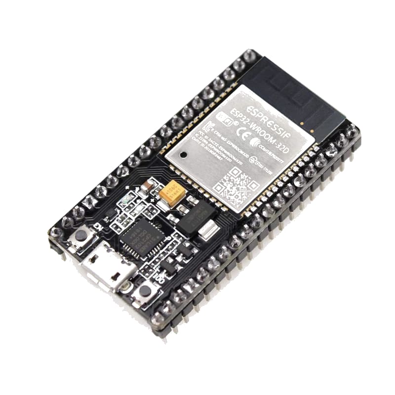
ESP32 Pinout

ESP8266 Pinout

ESP01 Pinout

Schematic
Connect the ESP8266/ESP32 to the Arduino as follows:
ESP-01 (ESP8266) minimal wiring
ESP-01                Arduino
------                -------
VCC           -->     3.3V (NOT 5V!)
GND           -->     GND
TX            -->     Digital Pin 3 (Arduino RX)
RX            -->     via voltage divider  -->  Digital Pin 2 (Arduino TX)
CH_PD (EN)    -->     3.3V (enable chip)
GPIO0         -->     HIGH (or leave floating for normal run mode)
RST           -->     3.3V (via 10 kΩ pull-up — optional)

Voltage divider on RX:
  Arduino pin 2 --/\/\-- ESP-01 RX
                  1 kΩ
                    |
  ESP-01 RX   --/\/\-- GND
                  2.2 kΩ
The ESP8266 operates at 3.3V and its RX pin is not 5V tolerant. A voltage divider is essential. Many ESP-01 modules draw more current than the Arduino 3.3V regulator can supply (~300 mA vs 150 mA max) — use an external 3.3V regulator (e.g., AMS1117-3.3).
NodeMCU / Wemos D1 wiring
NodeMCU and Wemos D1 boards have onboard USB-UART and voltage regulators. Connect them to the Arduino as simple serial devices:
NodeMCU               Arduino
-------               -------
TX (D10)      -->     Digital Pin 3  (Arduino RX)
RX (D9)       -->     Digital Pin 2  (Arduino TX)
GND           -->     GND
VU (5V)       -->     5V
NodeMCU/Wemos boards accept 5V on the VU/VIN pin and regulate it down internally. They can be powered from the Arduino 5V pin.
Pin Map
ESP-01
| ESP-01 Pin | Name | Connection |
|---|---|---|
| VCC | Power | 3.3V (external regulator) |
| GND | Ground | GND |
| TX | Transmit | Pin 3 (Arduino RX) |
| RX | Receive | Pin 2 via voltage divider |
| CH_PD (EN) | Chip enable | 3.3V |
| GPIO0 | Boot mode | HIGH (normal run) |
| RST | Reset | 3.3V via 10 kΩ |
NodeMCU / Wemos D1
| Module Pin | Name | Connection |
|---|---|---|
| VU (VIN) | Power | 5V |
| GND | Ground | GND |
| TX (D10) | Transmit | Pin 3 (Arduino RX) |
| RX (D9) | Receive | Pin 2 (Arduino TX) |
Install necessary Library
The ESP8266 communicates via standard AT commands over serial. No external Arduino library is strictly required — use SoftwareSerial for basic communication.
However, the ESP8266WiFi library by Espressif (used when programming the ESP directly) is not usable here. Instead, use the WiFiEsp library by bportaluri or AT command strings directly:
arduino-cli lib install "WiFiEsp"
This tutorial uses direct AT commands for maximum compatibility.
Code with complete explanation
This sketch connects the ESP8266 to a Wi-Fi network, fetches a web page, and hosts a simple TCP server. The Arduino sends AT commands to the ESP and parses responses.
#include <SoftwareSerial.h>

SoftwareSerial esp(3, 2); // RX, TX (Arduino pins)

void setup()
{
  Serial.begin(9600);
  esp.begin(115200); // Default ESP8266 baud rate (ESP32 often 115200 too)

  Serial.println("ESP8266 Wi-Fi Test");

  // Test communication
  sendCommand("AT", "OK", 2000);

  // Set to station mode
  sendCommand("AT+CWMODE=1", "OK", 2000);

  // Connect to Wi-Fi
  String connectCmd = "AT+CWJAP=\"Your_SSID\",\"Your_Password\"";
  sendCommand(connectCmd, "OK", 10000);

  // Get IP address
  sendCommand("AT+CIFSR", "OK", 2000);

  Serial.println("Ready. Type commands or wait for HTTP test.");
}

void loop()
{
  // TCP connection to example.com
  sendCommand("AT+CIPSTART=\"TCP\",\"example.com\",80", "CONNECT", 5000);

  // HTTP GET request
  String httpRequest = "GET / HTTP/1.1\r\nHost: example.com\r\nConnection: close\r\n\r\n";
  String sendCmd = "AT+CIPSEND=" + String(httpRequest.length());
  sendCommand(sendCmd, ">", 3000);

  esp.print(httpRequest);
  delay(3000);

  // Read and print response
  while (esp.available())
  {
    Serial.write(esp.read());
  }

  sendCommand("AT+CIPCLOSE", "OK", 2000);

  delay(10000);
}

// Send an AT command and wait for a response
void sendCommand(String command, String expected, unsigned long timeout)
{
  Serial.print("> ");
  Serial.println(command);

  esp.println(command);

  String response = "";
  unsigned long start = millis();

  while (millis() - start < timeout)
  {
    if (esp.available())
    {
      char c = esp.read();
      response += c;
      Serial.write(c);
    }
  }

  if (response.indexOf(expected) != -1)
  {
    Serial.println(" [OK]");
  }
  else
  {
    Serial.println(" [TIMEOUT]");
  }
}
ESP-01 initialisation sequence
If your ESP-01 does not respond to AT commands, try the following manual reset sequence in setup():
void setup()
{
  pinMode(espResetPin, OUTPUT);
  digitalWrite(espResetPin, LOW);
  delay(100);
  digitalWrite(espResetPin, HIGH);
  delay(1000);

  esp.begin(115200);
  sendCommand("AT", "OK", 2000);
}
Web server on the ESP
To turn the ESP into a web server that the Arduino controls:
void setupServer()
{
  // Start TCP server on port 80
  sendCommand("AT+CIPSERVER=1,80", "OK", 2000);

  // Set multiple connections mode
  sendCommand("AT+CIPMUX=1", "OK", 2000);
}

void checkClient()
{
  if (esp.available())
  {
    String data = esp.readString();

    if (data.indexOf("+IPD") != -1)
    {
      // Parse connection ID
      int connId = data.substring(data.indexOf("+IPD,") + 5, data.indexOf(",")).toInt();

      // Send HTTP response
      String response = "HTTP/1.1 200 OK\r\nContent-Type: text/html\r\n\r\n";
      response += "<h1>Arduino + ESP8266</h1>";
      response += "<p>Analog: ";
      response += analogRead(A0);
      response += "</p>";

      String sendCmd = "AT+CIPSEND=" + String(connId) + "," + String(response.length());
      sendCommand(sendCmd, ">", 2000);
      esp.print(response);
      delay(500);

      sendCommand("AT+CIPCLOSE=" + String(connId), "OK", 2000);
    }
  }
}
Code breakdown
SoftwareSerial esp(3, 2)— creates a software serial connection to the ESP module. Pin 3 (RX) gets ESP TX, pin 2 (TX) sends to ESP RX.esp.begin(115200)— sets the baud rate for ESP communication. ESP8266 defaults to 115200. Some modules use 9600 — if AT commands get no response, try 9600.AT— basic attention command, expectsOK.AT+CWMODE=1— sets Wi-Fi mode to station (client). Mode 2 = soft AP, Mode 3 = both.AT+CWJAP="SSID","PASS"— connects to a Wi-Fi network. Takes 5–15 seconds.AT+CIFSR— queries the IP address.AT+CIPSTART="TCP","host",port— establishes a TCP connection.AT+CIPSEND=<length>— prepares to send data of the specified length.AT+CIPCLOSE— closes the TCP connection.AT+CIPSERVER=1,80— starts a TCP server on port 80.AT+CIPMUX=1— enables multiple connections (required for server mode).+IPD,<id>,<len>:<data>— unsolicited message when data arrives on a server connection.
Common AT commands
| Command | Description |
|---|---|
AT | Test |
AT+RST | Reset module |
AT+GMR | Firmware version |
AT+CWMODE? | Query Wi-Fi mode |
AT+CWLAP | List available APs |
AT+CWJAP="S","P" | Connect to AP |
AT+CWQAP | Disconnect from AP |
AT+CIFSR | Get IP address |
AT+CIPSTART=... | Open TCP/UDP connection |
AT+CIPSEND=<n> | Send n bytes |
AT+CIPCLOSE | Close connection |
AT+CIPMUX=1 | Enable multi-connection |
AT+CIPSERVER=1,80 | Start server on port 80 |
AT+CIPSTO=<sec> | Set server timeout |
Steps to perform this interfacing
- Connect the ESP8266/ESP32 to the Arduino as shown in the schematic. Use the voltage divider on the RX line for ESP-01.
- If using an ESP-01 with a 5V Arduino, use an external 3.3V regulator to power the ESP. The Arduino 3.3V pin cannot supply enough current.
- Copy the code into the Arduino IDE.
- Replace
Your_SSIDandYour_Passwordwith your Wi-Fi credentials. - Select the correct board and port (
Tools > BoardandTools > Port). - Upload the sketch to the Arduino.
- Open the Serial Monitor (
Tools > Serial Monitor, set baud rate to 9600). - Observe the AT commands being sent and the ESP responses. The sequence should end with the IP address printed.
- If
ATreturns nothing, power-cycle the ESP and check: baud rate (try 9600), voltage divider on RX, and external 3.3V power.
Troubleshooting no response from ESP
- Check that ESP VCC is 3.3V (measured with a multimeter).
- Check that CH_PD (EN) is pulled HIGH to 3.3V.
- Check the voltage divider on RX — measure voltage at ESP RX, it should be ~3.3V when Arduino TX is HIGH.
- Try swapping TX and RX connections.
- Test the ESP alone: connect it to a USB-TTL converter at 3.3V and open a serial terminal at 115200 baud. Send
AT— it should respondOK.
Caution
- 3.3V power: ESP8266/ESP32 modules require a 3.3V supply capable of delivering 300–500 mA (ESP8266) or up to 500 mA (ESP32). The Arduino 3.3V pin can only supply ~150 mA — enough for the module to power on but not enough for reliable Wi-Fi transmission. Always use an external 3.3V regulator (AMS1117-3.3 or similar) when using an ESP-01 with an Arduino Uno/Nano. NodeMCU and Wemos D1 boards include their own regulators and can be powered from 5V.
- RX voltage divider: The ESP8266 RX pin is 3.3V only and will be damaged by direct connection to a 5V Arduino TX pin. Always use a voltage divider (1 kΩ / 2.2 kΩ) or a logic level shifter. The ESP TX pin outputs 3.3V and is safe for Arduino inputs.
- Baud rate: ESP8266 modules typically ship with a default baud rate of 115200 (or 9600 for some variants). If
ATgets no response, cycle through common baud rates: 9600, 19200, 38400, 57600, 115200. You can change the baud rate permanently withAT+UART_DEF=9600,8,1,0,0and then reset. - Firmware version: Older ESP-01 modules may have outdated AT firmware that lacks modern commands. Update the firmware using the ESP8266 Flash Download Tool or Espressif’s
esptool.py. The current AT firmware version should be 1.7+ for ESP8266 and 2.1+ for ESP32. - Current spikes: The ESP8266 draws short current spikes of up to 400 mA during Wi-Fi transmission (802.11 b/g/n). These spikes can cause the supply voltage to dip if insufficiently regulated, leading to spontaneous resets. Use a 100–470 µF capacitor across the ESP’s VCC and GND to absorb the spikes.
- Stacking with ESP8266/ESP32 core: If you find AT commands limiting, consider programming the ESP module directly using the Arduino core for ESP8266/ESP32. This gives you full control over Wi-Fi, TCP/IP, and GPIOs on the ESP, and you can communicate with the Arduino via I2C or serial instead of AT commands. This is the preferred approach for most production projects.
- GPIO0 and GPIO2: On the ESP-01, GPIO0 and GPIO2 must be pulled HIGH for normal boot. If GPIO0 is LOW at boot, the chip enters firmware download mode. If GPIO2 is LOW, it may not boot correctly. Use 10 kΩ pull-up resistors to 3.3V on both pins.