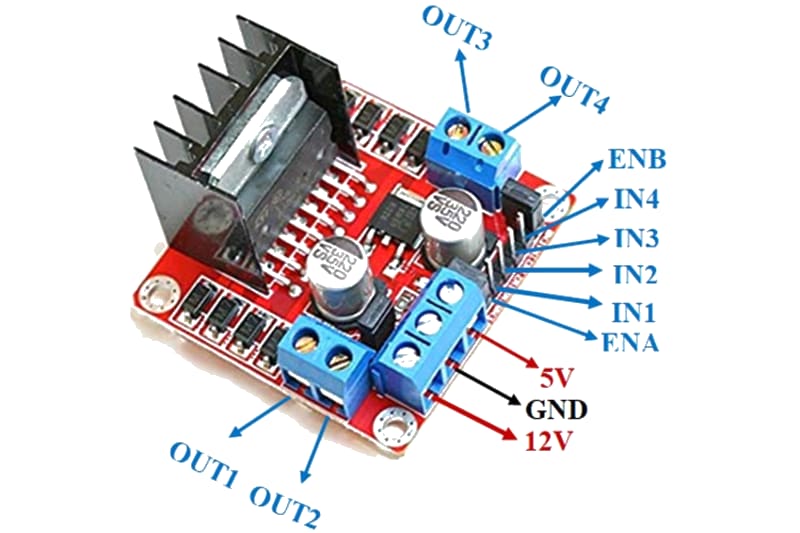
L298N Motor Driver – Dual H-bridge driver
The L298N is a dual H-bridge motor driver IC that can control the direction and speed of two DC motors independently (or one bipolar stepper motor). Each channel can deliver up to 2 A continuous current at motor voltages of 5–35 V. Direction is controlled via logic inputs (IN1–IN4), and speed is controlled via PWM on the enable pins (ENA, ENB). The module is widely used in robotics platforms, tank drives, conveyor belts, and automated gate systems.
For this interfacing you need the following components:
- Arduino board (Uno, Nano, Mega, etc.)
- L298N motor driver module
- Two DC motors (6–12V, or one bipolar stepper motor)
- External power supply (6–12V, rated for motor current)
- Breadboard and jumper wires
- USB cable to connect Arduino to your computer
Schematic
Connect the L298N module to the Arduino and motors as follows:
L298N Module          Arduino
------------          -------
IN1           -->     Digital Pin 5
IN2           -->     Digital Pin 6
IN3           -->     Digital Pin 10
IN4           -->     Digital Pin 11
ENA           -->     Digital Pin 9 (PWM)
ENB           -->     Digital Pin 3 (PWM)

5V            -->     5V (if jumper OFF) or leave disconnected (jumper ON)
GND           -->     GND (common)

VS (12V)      -->     External PSU (+)
GND           -->     External PSU (-)

OUT1, OUT2    -->     DC Motor A (polarity determines direction)
OUT3, OUT4    -->     DC Motor B
Jumper configuration
The L298N module has a jumper that controls the onboard 5V regulator:
- Jumper ON (default): The 5V regulator is enabled. The module outputs 5V on the 5V pin (can power the Arduino if VS ≥ 7V). Do not connect Arduino 5V to this pin — only one source should supply 5V.
- Jumper OFF: The 5V regulator is disabled. You must supply 5V to the 5V pin from the Arduino (or another 5V supply). Use this when VS is between 5–7V (too low for the regulator) or when you want the Arduino to power the logic.
For this tutorial, keep the jumper ON and do not connect the module 5V pin to the Arduino.
Pin Map
| Module Pin | Name | Arduino Connection |
|---|---|---|
| IN1 | Motor A direction input 1 | Pin 5 |
| IN2 | Motor A direction input 2 | Pin 6 |
| IN3 | Motor B direction input 1 | Pin 10 |
| IN4 | Motor B direction input 2 | Pin 11 |
| ENA | Motor A speed (PWM) | Pin 9 |
| ENB | Motor B speed (PWM) | Pin 3 |
| 5V | Logic supply (output or input) | (depends on jumper) |
| GND | Ground | GND |
| VS | Motor supply voltage | 6–12V DC |
| OUT1, OUT2 | Motor A output | DC motor A |
| OUT3, OUT4 | Motor B output | DC motor B |
Motor direction truth table
| IN1 | IN2 | Motor A behaviour |
|---|---|---|
| LOW | LOW | Brake (coast) |
| HIGH | LOW | Forward |
| LOW | HIGH | Backward |
| HIGH | HIGH | Brake (active stop) |
Same logic applies to IN3/IN4 for Motor B.
Enable pin behaviour
| ENA / ENB (PWM) | Motor state |
|---|---|
| LOW (0) | Disabled (free-running) |
| HIGH (255) | Full speed |
| PWM value (0–255) | Speed-controlled |
Install necessary Library
No external library is required. The L298N uses standard digitalWrite() and analogWrite() functions built into Arduino.
For convenience, the RoboClaw or AFMotor libraries offer higher-level interfaces — this tutorial uses the direct approach for full control.
Code with complete explanation
This sketch controls two DC motors independently. Motor A runs forward and backward at varying speeds while Motor B follows a separate pattern.
// Motor A control pins
const int enA = 9;
const int in1 = 5;
const int in2 = 6;

// Motor B control pins
const int enB = 3;
const int in3 = 10;
const int in4 = 11;

void setup()
{
  // Set all pins as outputs
  pinMode(enA, OUTPUT);
  pinMode(in1, OUTPUT);
  pinMode(in2, OUTPUT);

  pinMode(enB, OUTPUT);
  pinMode(in3, OUTPUT);
  pinMode(in4, OUTPUT);

  // Disable both motors initially
  digitalWrite(enA, LOW);
  digitalWrite(enB, LOW);

  Serial.begin(9600);
  Serial.println("L298N Motor Driver Test");
  Serial.println();
}

void loop()
{
  // --- Motor A: ramp up forward, then ramp down ---
  Serial.println("Motor A: Forward ramp");

  digitalWrite(in1, HIGH);
  digitalWrite(in2, LOW);

  for (int speed = 0; speed <= 255; speed += 5)
  {
    analogWrite(enA, speed);
    delay(30);
  }

  for (int speed = 255; speed >= 0; speed -= 5)
  {
    analogWrite(enA, speed);
    delay(30);
  }

  // --- Motor A: backward ramp ---
  Serial.println("Motor A: Backward ramp");

  digitalWrite(in1, LOW);
  digitalWrite(in2, HIGH);

  for (int speed = 0; speed <= 255; speed += 5)
  {
    analogWrite(enA, speed);
    delay(30);
  }

  for (int speed = 255; speed >= 0; speed -= 5)
  {
    analogWrite(enA, speed);
    delay(30);
  }

  // Stop Motor A
  digitalWrite(in1, LOW);
  digitalWrite(in2, LOW);
  delay(500);

  // --- Motor B: independent pattern ---
  Serial.println("Motor B: Alternating direction");

  for (int i = 0; i < 3; i++)
  {
    // Forward, increasing speed
    digitalWrite(in3, HIGH);
    digitalWrite(in4, LOW);

    for (int speed = 0; speed <= 255; speed += 20)
    {
      analogWrite(enB, speed);
      delay(50);
    }

    delay(200);

    // Backward, increasing speed
    digitalWrite(in3, LOW);
    digitalWrite(in4, HIGH);

    for (int speed = 0; speed <= 255; speed += 20)
    {
      analogWrite(enB, speed);
      delay(50);
    }

    delay(200);
  }

  // Stop Motor B
  digitalWrite(in3, LOW);
  digitalWrite(in4, LOW);
  delay(1000);
}
Code breakdown
digitalWrite(in1, HIGH)/digitalWrite(in2, LOW)— sets the direction for Motor A. The truth table above defines the four possible states.analogWrite(enA, speed)— sets the PWM duty cycle on the enable pin (0–255) to control the motor speed. 0 = stopped, 255 = full speed.digitalWrite(enA, LOW)— disables the motor completely (the H-bridge outputs are high-impedance, letting the motor coast).- The loop first ramps Motor A forward (speed 0 → 255 → 0), then backward (same ramp), then runs Motor B through three cycles of forward-speed-increase, pause, backward-speed-increase.
Controlling a single motor from Serial Monitor
void loop()
{
  if (Serial.available())
  {
    int speed = Serial.parseInt();

    if (speed > 0)
    {
      digitalWrite(in1, HIGH);
      digitalWrite(in2, LOW);
    }
    else if (speed < 0)
    {
      digitalWrite(in1, LOW);
      digitalWrite(in2, HIGH);
      speed = -speed;
    }
    else
    {
      digitalWrite(in1, LOW);
      digitalWrite(in2, LOW);
    }

    speed = constrain(speed, 0, 255);
    analogWrite(enA, speed);

    Serial.print("Speed: ");
    Serial.println(speed);
  }
}
Using the L298N with a bipolar stepper motor
The L298N can drive a bipolar stepper motor (e.g., NEMA 17) using the built-in Stepper library:
#include <Stepper.h>

const int stepsPerRev = 200; // NEMA 17 (1.8° per step)

// Pin order: IN1, IN3, IN2, IN4 (for L298N)
Stepper stepperMotor(stepsPerRev, 5, 10, 6, 11);

void setup()
{
  stepperMotor.setSpeed(60); // RPM
}

void loop()
{
  stepperMotor.step(stepsPerRev); // Forward one revolution
  delay(1000);
  stepperMotor.step(-stepsPerRev); // Backward one revolution
  delay(1000);
}
Steps to perform this interfacing
- Connect the L298N module to the Arduino and motors as shown in the schematic.
- Ensure the L298N module jumper is ON (5V regulator enabled).
- Connect the external motor power supply to VS and GND on the L298N. For two small DC motors (6V each), a 9V battery or 7.5V adapter works well.
- Connect the Arduino GND to the L298N GND (this is essential for the logic signals to work).
- Do not connect the L298N 5V pin to the Arduino (the jumper enables the onboard regulator).
- Copy the code into the Arduino IDE.
- Select the correct board and port (
Tools > BoardandTools > Port). - Upload the sketch to the Arduino.
- Observe Motor A ramping up and down forward, then backward, and Motor B alternating direction at increasing speeds.
Testing each motor individually
If a motor does not move, test each channel:
- Disconnect both motors.
- Set IN1 = HIGH, IN2 = LOW, ENA = HIGH.
- Measure voltage between OUT1 and OUT2 with a multimeter — you should see the motor supply voltage.
- If no voltage, check the enable pin jumper (ENA must have a jumper or be driven HIGH).
Caution
- Power supply: The L298N can deliver up to 2 A per channel, but this requires a power supply capable of supplying the full motor current. A 9V battery may work for one small motor but will drain quickly under load. Use a benchtop supply or a lead-acid battery for sustained use. The L298N’s voltage drop (around 2 V per channel at 1 A) means a 6V motor will only receive ~4V — account for this in your power budget.
- Heatsink required: The L298N IC dissipates significant heat when driving motors at high current. The module ships with a heatsink — ensure it is properly attached. Without adequate cooling, the L298N enters thermal shutdown (outputs disabled) at approximately 170°C.
- Flyback diodes: The L298N module includes flyback diodes (1N4007 or similar) to protect against back-EMF from the motors. If you are using a bare L298N IC (not a module), you must add these diodes externally — one from each output to VS and one from each output to GND.
- 5V regulator jumper: When the jumper is ON and VS is at least 7V, the module outputs 5V on the 5V pin. This can power the Arduino (connect 5V → Arduino 5V, GND → Arduino GND). However, if VS drops below 7V, the 5V output becomes unstable. In that case, remove the jumper and supply 5V from the Arduino to the logic pin.
- Common ground: The L298N GND must always be connected to the Arduino GND. Without this connection, the logic inputs are floating and the motor may run erratically or not at all.
- Stall current: If a motor is physically blocked, the current through the L298N can exceed 2 A per channel, potentially damaging the IC. Use current limiting (e.g., a fuse or a current-sense circuit) if the motor may stall under normal operation.
- PWM frequency: The default
analogWrite()frequency on Arduino is 490 Hz (pins 3, 9, 10, 11) or 980 Hz (pins 5, 6). These frequencies work well with the L298N. Using higher PWM frequencies (e.g., withTimer1or thePWMlibrary) may reduce audible noise from the motor but can also increase switching losses in the L298N.