ADXL335/ADXL345 Accelerometer
The ADXL335 is a 3-axis analog accelerometer (±3 g) that outputs three voltage signals proportional to acceleration on X, Y, and Z axes. It requires three analog pins and no library. The ADXL345 is a digital 3-axis accelerometer (±2/±4/±8/±16 g) with I²C or SPI interface, onboard FIFO, tap/double-tap detection, and activity/inactivity sensing. Both are used for orientation detection, tilt sensing, shake detection, and motion logging.

For this interfacing you need the following components:
- Arduino board (Uno, Nano, Mega, etc.)
- ADXL335 module (GY-61) OR ADXL345 module (GY-291)
- Breadboard and jumper wires
- USB cable to connect Arduino to your computer
Schematic
ADXL335 (analog)
GY-61 Module          Arduino
-----------           -------
VCC           -->     5V
GND           -->     GND
X             -->     A0 (analog)
Y             -->     A1 (analog)
Z             -->     A2 (analog)
The ADXL335 outputs 0–5V signals proportional to ±3 g. At rest on a flat surface: X ≈ 1.65V (ADC 338), Y ≈ 1.65V (338), Z ≈ 2.45V (ADC 500) — Z shows 1 g downward.
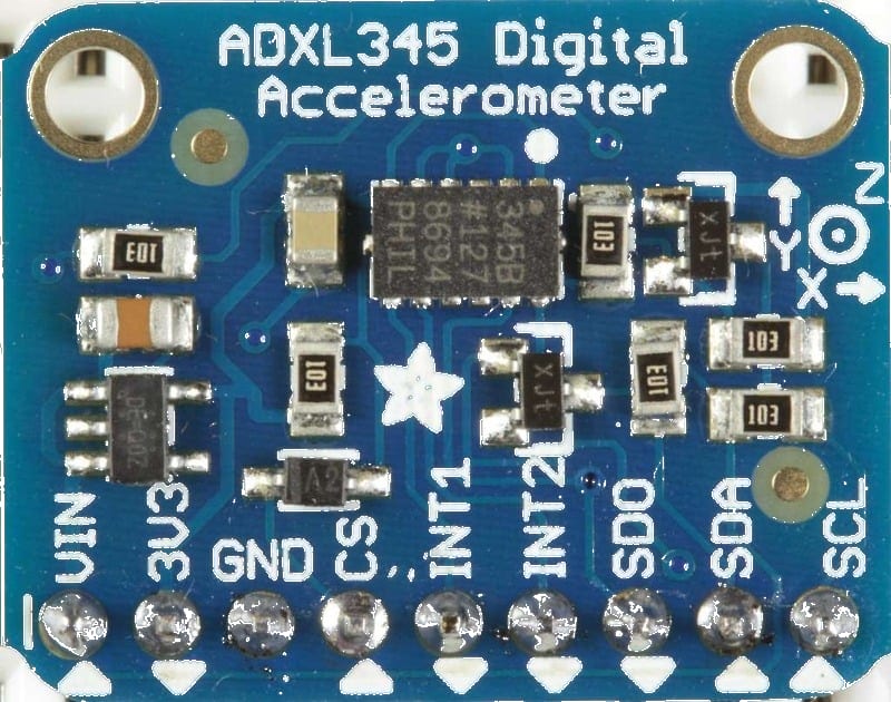
ADXL345 (I²C)
GY-291 Module         Arduino
-------------         -------
VCC           -->     3.3V (check module — some accept 5V)
GND           -->     GND
SCL           -->     A5 (Uno) / SCL (Mega)
SDA           -->     A4 (Uno) / SDA (Mega)
ADXL345 (SPI)
GY-291                Arduino
------                -------
CS            -->     Pin 10
MOSI          -->     Pin 11
MISO          -->     Pin 12
SCLK          -->     Pin 13
VCC           -->     3.3V
GND           -->     GND
Pin Map
ADXL335
| Module Pin | Arduino Pin |
|---|---|
| VCC | 5V |
| GND | GND |
| X | A0 |
| Y | A1 |
| Z | A2 |
ADXL345 (I²C)
| Module Pin | Arduino Pin |
|---|---|
| VCC | 3.3V or 5V |
| GND | GND |
| SCL | A5 (Uno), 21 (Mega) |
| SDA | A4 (Uno), 20 (Mega) |
- I²C address: 0x53 (default, ADDR pin LOW) or 0x1D (ADDR HIGH).
Install necessary Library
ADXL335
No library needed — use analogRead().
ADXL345
Install the Adafruit ADXL345 library by Adafruit via the Library Manager:
arduino-cli lib install "Adafruit ADXL345"
Dependency: Adafruit Unified Sensor.
Code with complete explanation
ADXL335 (analog) — tilt angle and motion
#define X_PIN A0
#define Y_PIN A1
#define Z_PIN A2

// Calibration offsets (at rest, flat)
const float zeroX = 338.0;
const float zeroY = 338.0;
const float zeroZ = 500.0;  // 1 g on Z

const float sens = 102.3;   // ADC points per g (1023 / 3 g / 2)

void setup()
{
  Serial.begin(9600);
  Serial.println("ADXL335 Accelerometer");
}

void loop()
{
  float x = (analogRead(X_PIN) - zeroX) / sens;
  float y = (analogRead(Y_PIN) - zeroY) / sens;
  float z = (analogRead(Z_PIN) - zeroZ) / sens;

  float roll  = atan2(y, sqrt(x * x + z * z)) * 180.0 / PI;
  float pitch = atan2(-x, sqrt(y * y + z * z)) * 180.0 / PI;

  Serial.print("X: ");
  Serial.print(x, 2);
  Serial.print(" g  Y: ");
  Serial.print(y, 2);
  Serial.print(" g  Z: ");
  Serial.print(z, 2);
  Serial.print(" g  Roll: ");
  Serial.print(roll, 1);
  Serial.print("°  Pitch: ");
  Serial.print(pitch, 1);
  Serial.println("°");

  delay(200);
}
ADXL345 (digital) — I²C
#include <Wire.h>
#include <Adafruit_Sensor.h>
#include <Adafruit_ADXL345_U.h>

Adafruit_ADXL345_Unified accel = Adafruit_ADXL345_Unified(12345);

void setup()
{
  Serial.begin(9600);

  if (!accel.begin())
  {
    Serial.println("ADXL345 not found!");
    while (1) {}
  }

  // Set range: ±2, ±4, ±8, or ±16 g
  accel.setRange(ADXL345_RANGE_2_G);

  Serial.println("ADXL345 Accelerometer");
}

void loop()
{
  sensors_event_t event;
  accel.getEvent(&event);

  float x = event.acceleration.x;
  float y = event.acceleration.y;
  float z = event.acceleration.z;

  // Calculate tilt angles
  float roll  = atan2(y, sqrt(x * x + z * z)) * 180.0 / PI;
  float pitch = atan2(-x, sqrt(y * y + z * z)) * 180.0 / PI;

  Serial.print("X: ");
  Serial.print(x, 2);
  Serial.print(" m/s²  Y: ");
  Serial.print(y, 2);
  Serial.print(" m/s²  Z: ");
  Serial.print(z, 2);
  Serial.print(" m/s²  Roll: ");
  Serial.print(roll, 1);
  Serial.print("°  Pitch: ");
  Serial.print(pitch, 1);
  Serial.println("°");

  delay(200);
}
Tap detection (ADXL345)
void setup()
{
  accel.begin();
  accel.setRange(ADXL345_RANGE_2_G);

  // Configure tap detection
  accel.setTapThreshold(80);    // Threshold (mg) — trigger level
  accel.setTapDuration(15);     // Duration (ms) — window for tap
  accel.setDoubleTapLatency(40);  // Latency between taps (ms)
  accel.setDoubleTapWindow(200);  // Window for double-tap (ms)

  accel.enableTapDetection(
    ADXL345_TAP_XYZ,          // Enable on X, Y, Z
    ADXL345_SINGLE_AND_DOUBLE // Single + double tap
  );
}

void loop()
{
  accel.getEvent(&event);

  if (event.tap.type)
  {
    if (event.tap.type == ADXL345_TAP_SINGLE)
      Serial.println("Single tap detected");

    if (event.tap.type == ADXL345_TAP_DOUBLE)
      Serial.println("Double tap detected");
  }
}
Code breakdown (ADXL335)
zeroX/zeroY/zeroZ— calibration offsets: the ADC reading when the sensor is at rest on a flat, level surface. These account for sensor manufacturing tolerances and should be calibrated per unit.sens— sensitivity in ADC counts per g. For ±3 g range: 1023 ADC / (2 × 3 g) ≈ 170.5 counts/g. However, the sensor outputs 0.5V at 0 g and 3.5V at full scale, so the effective range of the ADC for the accelerometer output is approx 0.5–3.5V → ADC 102–716 → 614 counts / 6 g = 102.3 counts/g.atan2(y, sqrt(x² + z²))— calculates roll angle from the gravity vector.atan2(-x, sqrt(y² + z²))— calculates pitch angle.
Code breakdown (ADXL345)
accel.getEvent(&event)— fillsevent.acceleration.x/y/zwith acceleration in m/s². (1 g ≈ 9.81 m/s².)accel.setRange(range)— selects the full-scale range. ±2 g is best for tilt sensing (highest resolution).- Tap detection configures thresholds and duration for the on-chip tap recognition. The FIFO buffer can store up to 32 events.
- The
Adafruit_ADXL345_Unifiedclass uses the Adafruit Unified Sensor abstraction providing standardisedsensors_event_tstructures.
Steps to perform this interfacing
- Connect the ADXL335 (analog) or ADXL345 (I²C/SPI) to the Arduino.
- For ADXL345, install the Adafruit ADXL345 library.
- Copy the relevant code into the Arduino IDE.
- Select the correct board and port (
Tools > BoardandTools > Port). - Upload the sketch to the Arduino.
- Open the Serial Monitor (baud 9600).
- Tilt the sensor — observe how X, Y, Z values change and the roll/pitch angles respond.
- Rest the sensor flat — Z should show ≈ 1 g (ADXL345: 9.81 m/s²), X and Y near 0.
- For ADXL345 tap detection: tap the sensor firmly twice — observe “Double tap detected”.
Caution
- ADXL335 voltage output range: The ADXL335 outputs 0.5V at 0 g (no acceleration) and 3.5V at full scale (±3 g). This is within the Arduino’s 0–5V ADC range. At rest on a flat surface, Z ≈ 2.45V (1 g), corresponding to ADC ≈ 500. The minimum output (0.5V) means the ADC never reads below ∼102 — subtract this offset when calibrating.
- ADXL345 3.3V logic: The ADXL345 is a 3.3V device. Its I²C/SPI logic levels must not exceed 3.6V. Most breakout boards include a 3.3V regulator and level shifters, but verify before connecting VCC to 5V. If no level shifters exist, power from 3.3V and add a voltage divider on the Arduino’s 5V I²C/SPI lines.
- Calibration offsets: Both sensors have offset errors of ±50–100 mg (milli-g) that vary per axis. For accurate tilt sensing (< 5° error), calibrate by recording 100 samples in each of 6 orientations (each axis up/down) and average the offsets. The code above uses nominal values that work for demonstration but introduce 5–10° errors on individual units.
- Vibration vs tilt: An accelerometer cannot distinguish between acceleration due to tilt (gravity) and acceleration due to motion (vibration). When the sensor is in motion, the tilt angle calculation becomes inaccurate because the measured vector is the sum of gravity + linear acceleration. For tilt-compensated orientation with motion, fuse with a gyroscope (see MPU6050 tutorial).
- Soldering the ADXL335: The ADXL335 is available as a surface-mount IC on the GY-61 breakout. The breakout’s pins are 2.54 mm pitch and breadboard-friendly. Handle by the edges — the sensor is an MEMS structure that can be damaged by mechanical shock during soldering.
- ADXL345 FIFO: The 32-level FIFO buffer can be configured to store acceleration data in stream mode, triggered mode, or FIFO mode. This is useful for logging motion events without continuous CPU polling. Refer to the datasheet for FIFO configuration registers.
- I²C address conflict: The ADXL345’s default I²C address (0x53) may conflict with some other I²C sensors. If you need to change it, solder the ADDR pin to VCC for address 0x1D.