7-Segment LED Display (Single Digit)
A 7-segment display contains eight LEDs — seven segments (a–g) forming the digit and one optional decimal point (DP). Segments are arranged as a common cathode (CC, all cathodes tied to GND) or common anode (CA, all anodes tied to VCC). Each segment requires a current-limiting resistor. By turning on the correct combination of segments, digits 0–9 and some letters (A, b, C, d, E, F) can be displayed.

For this interfacing you need the following components:
- Arduino board (Uno, Nano, Mega, etc.)
- Single-digit 7-segment LED display (common cathode or common anode)
- 8 × 220 Ω resistors (or 100–330 Ω depending on brightness)
- Breadboard and jumper wires
- USB cable to connect Arduino to your computer
Schematic
Arduino       Resistors        7-Segment (CC)
-------       ---------        --------------
Pin 2  ----[220Ω]----  Segment a (pin A / 7)
Pin 3  ----[220Ω]----  Segment b (pin B / 6)
Pin 4  ----[220Ω]----  Segment c (pin C / 4)
Pin 5  ----[220Ω]----  Segment d (pin D / 2)
Pin 6  ----[220Ω]----  Segment e (pin E / 1)
Pin 7  ----[220Ω]----  Segment f (pin F / 9)
Pin 8  ----[220Ω]----  Segment g (pin G / 10)
Pin 9  ----[220Ω]----  Segment DP (pin DP / 5)
GND    ---------------- Common cathode(s)*
*Common cathode: connect both centre pins (3 and 8 on most 7-segment pinouts) to GND. Common anode: connect to 5V instead.
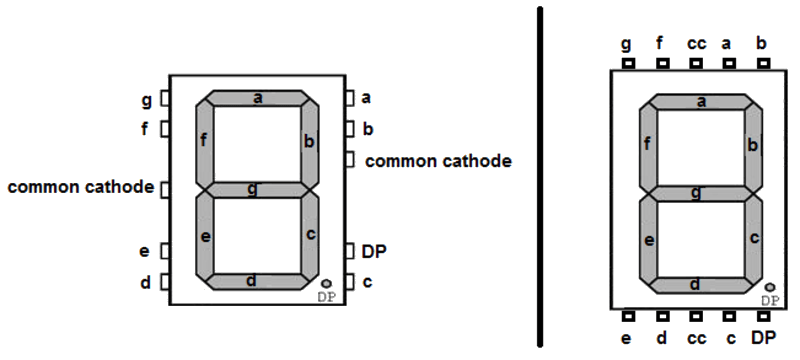
Pin Map
Standard 7-segment pinout (top view, pins numbered counterclockwise from top-left of the decimal-point side):
         aaaa
        f    b
        f    b
         gggg
        e    c
        e    c
         dddd   dp

Pin map (common cathode, 10-pin DIP):
 Pin 1 = Segment e
 Pin 2 = Segment d
 Pin 3 = Common cathode
 Pin 4 = Segment c
 Pin 5 = Segment DP
 Pin 6 = Segment b
 Pin 7 = Segment a
 Pin 8 = Common cathode
 Pin 9 = Segment f
 Pin 10 = Segment g
| Arduino Pin | Segment |
|---|---|
| 2 | a |
| 3 | b |
| 4 | c |
| 5 | d |
| 6 | e |
| 7 | f |
| 8 | g |
| 9 | DP |
Install necessary Library
No library is required. Segment control is done with digitalWrite() and a lookup table. For multiple digits (multiplexed), the SevSeg library by Dean Reading simplifies the process:
arduino-cli lib install "SevSeg"
Code with complete explanation
This sketch displays digits 0–9 and cycles through them using a button.
// Segment pin assignments (Arduino digital pins)
#define SEG_A  2
#define SEG_B  3
#define SEG_C  4
#define SEG_D  5
#define SEG_E  6
#define SEG_F  7
#define SEG_G  8
#define SEG_DP 9

#define BTN_PIN 10

// Segment array for easy indexing
const uint8_t segPins[8] = {SEG_A, SEG_B, SEG_C, SEG_D, SEG_E, SEG_F, SEG_G, SEG_DP};

// Segment patterns for digits 0–9 (common cathode: 1 = ON)
// Order: a, b, c, d, e, f, g, dp
const uint8_t digitPatterns[10][8] = {
  {1, 1, 1, 1, 1, 1, 0, 0},  // 0
  {0, 1, 1, 0, 0, 0, 0, 0},  // 1
  {1, 1, 0, 1, 1, 0, 1, 0},  // 2
  {1, 1, 1, 1, 0, 0, 1, 0},  // 3
  {0, 1, 1, 0, 0, 1, 1, 0},  // 4
  {1, 0, 1, 1, 0, 1, 1, 0},  // 5
  {1, 0, 1, 1, 1, 1, 1, 0},  // 6
  {1, 1, 1, 0, 0, 0, 0, 0},  // 7
  {1, 1, 1, 1, 1, 1, 1, 0},  // 8
  {1, 1, 1, 1, 0, 1, 1, 0},  // 9
};

int currentDigit = 0;

void setup()
{
  for (int i = 0; i < 8; i++)
  {
    pinMode(segPins[i], OUTPUT);
    digitalWrite(segPins[i], LOW);  // All segments off
  }

  pinMode(BTN_PIN, INPUT_PULLUP);
}

void loop()
{
  if (digitalRead(BTN_PIN) == LOW)
  {
    currentDigit = (currentDigit + 1) % 10;
    showDigit(currentDigit);
    delay(200);
  }
}

void showDigit(int digit)
{
  for (int s = 0; s < 7; s++)  // Skip DP (index 7)
  {
    digitalWrite(segPins[s], digitPatterns[digit][s]);
  }
}

void showNumber(int num, bool showDp)
{
  if (num < 0 || num > 9) return;

  for (int s = 0; s < 7; s++)
  {
    digitalWrite(segPins[s], digitPatterns[num][s]);
  }

  digitalWrite(SEG_DP, showDp ? HIGH : LOW);
}
Using the SevSeg library
#include <SevSeg.h>

SevSeg display;

void setup()
{
  byte numDigits = 1;
  byte digitPins[] = {};  // No digit select for single-digit
  byte segmentPins[] = {2, 3, 4, 5, 6, 7, 8, 9};  // a,b,c,d,e,f,g,dp
  bool resistorsOnSegments = true;
  bool updateWithDelays = false;
  bool leadingZeros = false;

  display.begin(COMMON_CATHODE, numDigits, digitPins, segmentPins,
                resistorsOnSegments, updateWithDelays, leadingZeros);
  display.setBrightness(100);
}

void loop()
{
  for (int i = 0; i < 10; i++)
  {
    display.setNumber(i, 0);  // digit, decimal places
    display.refreshDisplay();
    delay(1000);
  }
}
Code breakdown
digitPatterns[10][8]— lookup table mapping each digit (0–9) to the 8 segment states. For common cathode: 1 = segment ON, 0 = OFF. For common anode: invert all bits (1 → OFF, 0 → ON).showDigit(digit)— writes the segment pattern for a single digit to the output pins, skipping the decimal point.showNumber(num, showDp)— same but includes DP control.SevSeglibrary handles multiplexing and refresh automatically for single and multi-digit displays.- Each segment LED is lit by driving its anode HIGH and cathode LOW (common cathode). The 220 Ω resistor limits current to ≈ 10–15 mA per segment.
Common anode inversion
For common anode displays, invert the pattern:
void showDigitCA(int digit)
{
  for (int s = 0; s < 7; s++)
  {
    digitalWrite(segPins[s], digitPatterns[digit][s] ? LOW : HIGH);
  }
}
Steps to perform this interfacing
- Identify your display’s pinout with a multimeter (diode test mode) or reference the datasheet.
- Connect each segment pin through a 220 Ω resistor to an Arduino digital pin.
- Connect the common pin(s) to GND (CC) or 5V (CA).
- Copy the code into the Arduino IDE.
- Select the correct board and port (
Tools > BoardandTools > Port). - Upload the sketch to the Arduino.
- Observe the digit: it should display a single character (initial state is all off).
- Press the button (pin 10 to GND) to cycle through digits 0–9.
Identifying pin 1
Most 7-segment displays have pins numbered counterclockwise from pin 1, which is located to the left of the decimal point when the display faces you and the decimal point is at the bottom-right. Pin 1 is typically at the bottom-left. Use a multimeter: put it in diode test mode, touch the negative probe (black) to the common cathode pin, and the positive probe (red) to each segment pin — the corresponding segment lights up when you find it.
Caution
- Current-limiting resistor required: Each segment LED must have its own current-limiting resistor. Running a segment without a resistor will draw excessive current (potentially 50–100 mA), destroying both the segment and the Arduino pin in seconds. Do not use a single resistor on the common pin — this causes uneven brightness (digits with more segments on will be dimmer) and exceeds the pin’s current rating when all 8 segments are lit.
- Common cathode vs common anode wiring: Connecting a common cathode display to 5V (instead of GND) will keep all segments permanently off regardless of the pin states — the LEDs are reverse-biased. Conversely, a common anode display connected to GND will leave segments always faintly lit. Check before powering on.
- Maximum pin current: If all 7 segments plus DP are lit simultaneously at 15 mA each, the total current per common pin is 8 × 15 mA = 120 mA. For a common cathode display, this 120 mA flows through the common GND pin. The Arduino’s GND pin can handle this, but the common pin on the display is a single thin lead — ensure it is solidly connected and the solder joint is not stressed. For high brightness, consider a transistor driver on the common pin.
- Forward voltage per segment: Red segments have V_f ≈ 1.8V, green ≈ 2.1V. With a 5V supply and 220 Ω resistor: I = (5 - 1.8) / 220 ≈ 14.5 mA. This is within the Arduino pin’s 40 mA limit and the display’s typical 20 mA max rating. For 3.3V Arduinos, reduce resistors to 100 Ω (I ≈ (3.3 - 1.8) / 100 ≈ 15 mA) or use a boost converter.
- Static damage: 7-segment displays are LED-based and not particularly ESD-sensitive, but the driver IC in some multi-digit modules (MAX7219) can be damaged by static. Handle with normal ESD precautions.